Rapidly deployable flood defence system

a flood defence and rapid deployment technology, applied in the field of rapid deployment of flood barriers or diking systems, can solve the problems of requiring thousands of person hours to deploy and stack sandbags, burlap sandbags need to be removed or tend to rot or split, and achieve the effect of rapid and easy deploymen

Active Publication Date: 2020-12-31
PARSONS ROBERT JOHN
View PDF0 Cites 2 Cited by
  • Summary
  • Abstract
  • Description
  • Claims
  • Application Information

AI Technical Summary

Benefits of technology

[0007]The present invention seeks to overcome the disadvantages of prior art flood barriers by providing a portable flood barrier which may be rapidly and easily deployed, and which may be collapsed and stored for reuse, without the need for extensive resources, site preparation or large storage and handling facilities.

Problems solved by technology

Burlap-type sandbags suffer the disadvantage that they need to be first filled with sand, then sealed individually and conveyed to the site of a flood, resulting in enormous labour and logistic costs, and requiring thousands of person hours to deploy and stack the sandbags in place.
Once used and the flood waters have receded, the burlap sandbags need to be removed or they tend to rot or split.
Often, the sandbags are contaminated by sewage and other toxic waste that is extremely hazardous to humans and animals, and require extensive decontamination or special disposal arrangements.
Removal of the sandbags results in the same costs and resource requirements as the initial deployment.
Water filled cylindrical tube flood barriers, however, suffer various disadvantages of instability and often require extensive and costly decontamination after being collapsed for withdrawal and storage.
One type of currently used inflatable barriers filled with air, such as that disclosed in Canadian Patent Number CA 2,909,346 issued to Cintec International Ltd of the United Kingdom, are monolithic in design, particularly with respect to the barrier component and may be susceptible to catastrophic failure in the event that the barrier component becomes damaged.
The prior art cylindrical tubes suffer a further disadvantage in that the tubes are prone to rupture, not only from internal pressures, but also from puncture and tearing by logs and other debris swept along by the flood waters, and which may strike against the side of the inflated tube.

Method used


Image

  • Rapidly deployable flood defence system
  • Rapidly deployable flood defence system
  • Rapidly deployable flood defence system

Examples


Embodiment Construction

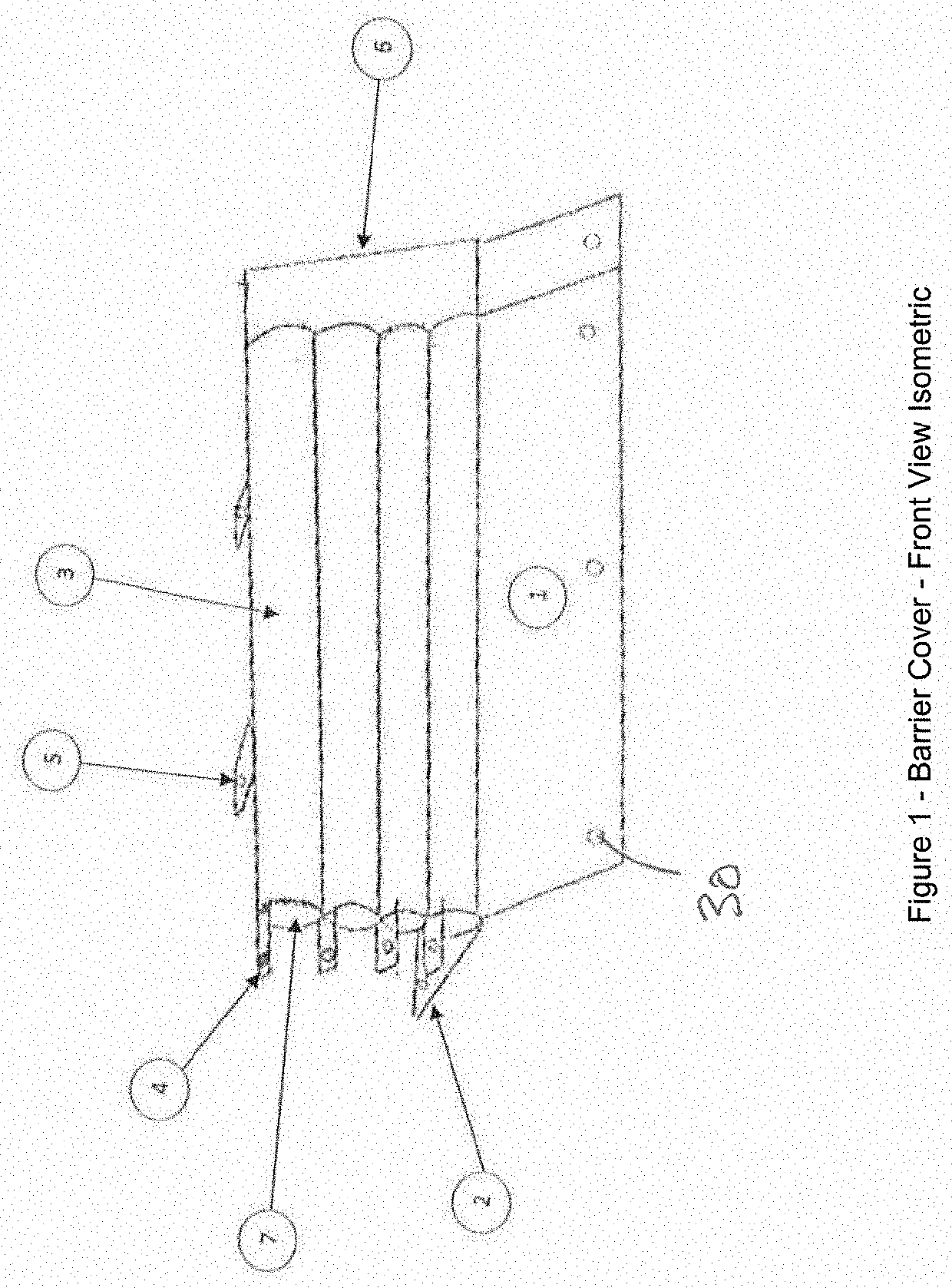
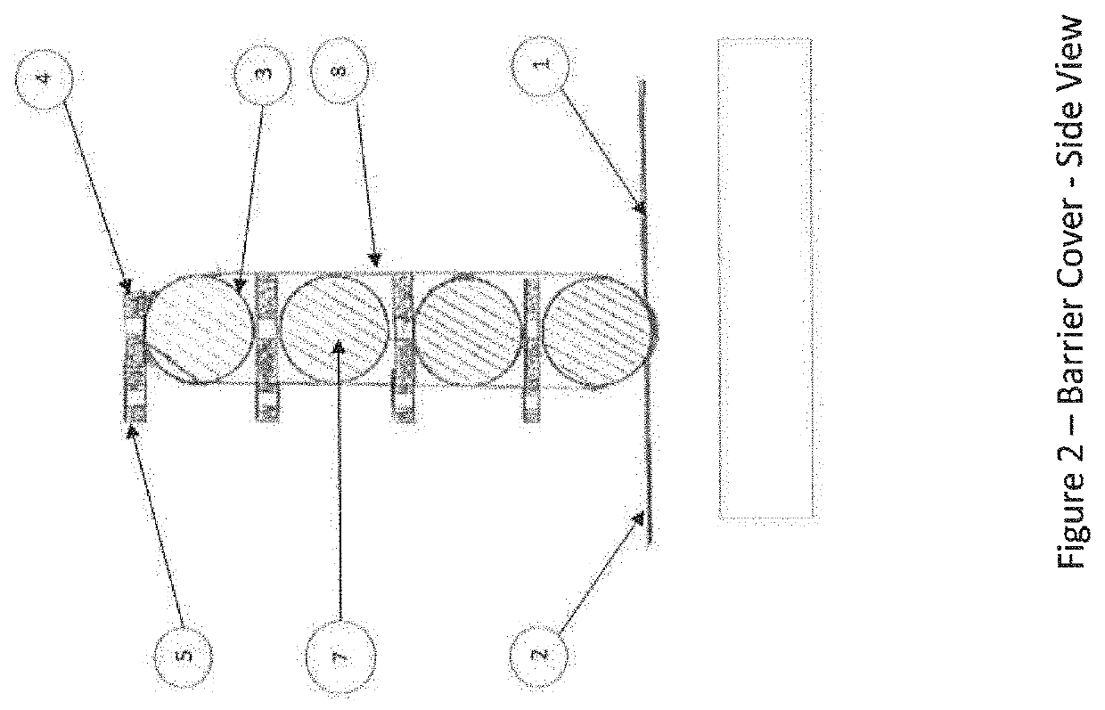
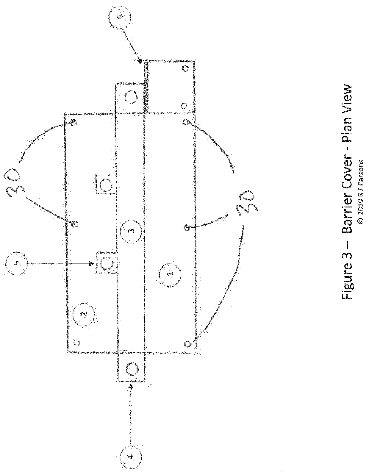
[0028]The rapidly deployable flood-defense system 11 comprises a barrier cover 8, as shown in FIGS. 1-4. The barrier cover 8 comprises a front apron 1, a rear apron 2, and a plurality of crossbeam housing tubes 3 for containment of the air inflatable crossbeams 7. The crossbeam housing tubes 3 are laterally-extending and stacked in a vertical direction.

[0029]As can be seen in the Figures, each crossbeam housing tube 3 includes an end retaining tab 4 at each end, and a plurality of rear support retaining tabs 5 which are spaced along the lateral length of each crossbeam housing tube 3. As can be seen especially in FIGS. 2 and 4, the rear support retaining tabs 5 of each crossbeam housing tube 3, are spaced apart identically to the rear support retaining tabs of the crossbeam housing above and below. This way, all of the rear support retaining tabs 5 line up in a generally vertical direction.

[0030]The barrier cover 8 is a textile component that is used to provide the overall structure...


PUM


Abstract

The present invention is a rapidly deployable flood defense system and method that has at least one barrier cover, each comprising a plurality of laterally-extending crossbeam housing tubes stacked generally vertically and housing an inflatable crossbeam disposed within the tube, an end retaining tab at each end of the tube, and a plurality of rear support retaining tabs spaced along the lateral length of the crossbeam housing tube; and a front apron and a rear apron. The system also has a plurality of support tubes and a plurality of additional support tubes positioned along the lateral length of the crossbeam housing tube. Each support tube held in the generally vertical direction by a base post and each and additional support tube positioned along the lateral length of the crossbeam housing tube having an additional base post positioned rearwardly.

Description

CROSS REFERENCE TO RELATED APPLICATION[0001]This application claims priority under 35 USC § 119 to U.S. Provisional Patent Application No. 62 / 886,721 filed on Jun. 26, 2019, the contents of which are hereby incorporated by reference in its entirety.FIELD OF THE INVENTION[0002]This present invention relates to a rapidly deployable flood barrier or diking system that, when used in combination with the staking system, may be quickly and easily positioned and inflated to provide a durable barrier to provide environmental remediation and contain rivers, lakes and other bodies of water reaching flood stage.BACKGROUND OF THE INVENTION[0003]The use of sand filled burlap bags has been the conventional means of containing flooding rivers for several centuries. Burlap-type sandbags suffer the disadvantage that they need to be first filled with sand, then sealed individually and conveyed to the site of a flood, resulting in enormous labour and logistic costs, and requiring thousands of person h...

Claims


Application Information

Patent Timeline
Patent Type & Authority Applications(United States)
IPC IPC(8): E02B3/10E02B7/20
CPCE02B3/108E02B7/20E06B2009/007E02B3/106E02B7/005Y02A10/30
Inventor PARSONS, ROBERT JOHN
Owner PARSONS ROBERT JOHN
Why Eureka
Try Eureka