Method and apparatus for suppression of noise due to transmitted signal instability in a coherent fiber optical sensor system

a fiber optic sensor and receiver technology, applied in the direction of converting sensor output optically, instruments, measurement devices, etc., can solve the problems of rayleigh backscattering, the duty cycle of interrogation signals, and the dominance of shot noise at the receiver, so as to suppress the noise induced by the transmitted signal

Active Publication Date: 2020-12-31
ALCATEL SUBMARINE NETWORKS
View PDF0 Cites 4 Cited by
  • Summary
  • Abstract
  • Description
  • Claims
  • Application Information

AI Technical Summary

Benefits of technology

[0011]It is an objective of the present innovation to overcome the presented limitations in the prior art. In particular, it is an objective to suppress the noise induced by the transmitted signal on the demodulated signals in a distributed sensing system.

Problems solved by technology

Particularly, naturally occurring and unavoidable density variations in the fiber gives rise to Rayleigh backscattering.
The disadvantage of the c-OTDR technique is that a duty-cycle of the interrogation signal is directly given by the number of sensor channels, e.g. a system with 1000 sensor channels gives a duty-cycle of only 0.1%.
Firstly, the shot noise at the receiver dominates for reflected signals from points at the far end of the sensor fiber due to very little reflected light.
This noise increases by the propagation loss in the fiber, and ultimately defines the range of the measurement.
The second major noise contribution is the source noise of the laser and the modulator, and particularly the frequency noise of the laser.
Even though, the source induced noise may be lowered by selecting a narrowband laser such as a fiber distributed feedback laser (DFB), it is still the dominant noise factor at short ranges.

Method used


Image

  • Method and apparatus for suppression of noise due to transmitted signal instability in a coherent fiber optical sensor system
  • Method and apparatus for suppression of noise due to transmitted signal instability in a coherent fiber optical sensor system
  • Method and apparatus for suppression of noise due to transmitted signal instability in a coherent fiber optical sensor system

Examples


Embodiment Construction

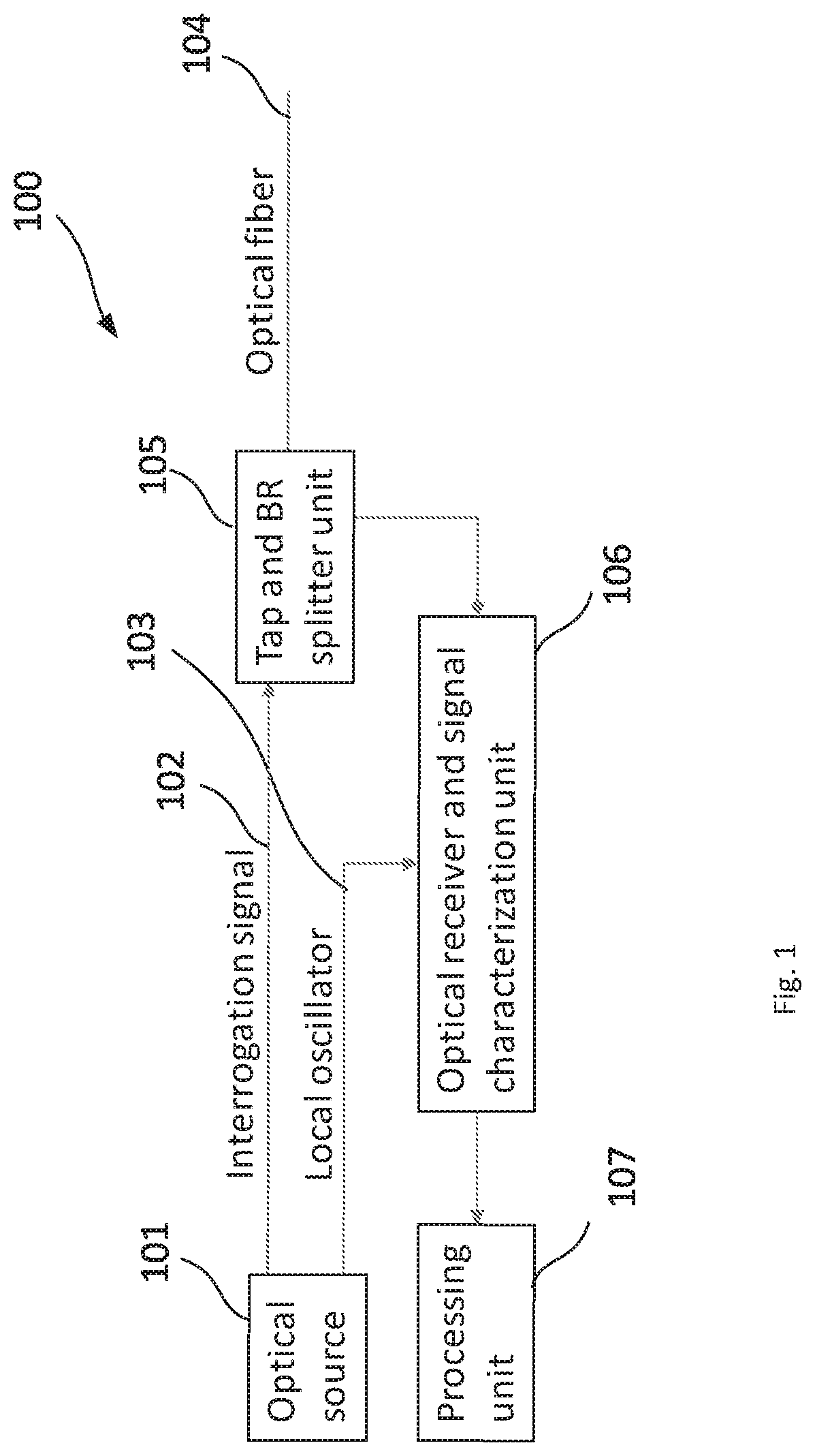
0 according to the invention, the system comprising an optical source 101 providing an interrogation signal 102 and an optical local oscillator 103. The optical local oscillator is directed to an optical receiver and signal characterization unit 106. The interrogation signal is being launched into the optical fiber 104 (called “sensor fiber” in the following) via a tap and backreflection unit 105. Note that the term “sensor fiber” here merely means the fiber to be interrogated, not necessarily that the fiber contains or forms sensors as such. For instance, in some embodiments, the sensor fiber may be a regular optical fiber, such as an SMF-28-type fiber. The interrogation signal 102 is launched into the sensor fiber 104 will be reflected from different sections of the sensor fiber and directed to the optical receiver and signal characterization unit 106 via the tap and backreflection unit 105. The optical receiver and signal characterization unit 106 mixes the reflected light with t...


PUM


Abstract

A method for measuring a response from an optical fiber providing distributed back reflections using a system comprising an optical source comprising a laser, an optical receiver and a processing unit is disclosed. The method comprises establishing initial parameters of a distributed back-reflection processing. The method also comprises generating an interrogation signal and an optical local oscillator using the optical source, the interrogation signal being represented by an interrogation phasor and the optical local oscillator being represented by a local oscillator phasor; transmitting the interrogation signal into the optical fiber; and mixing the optical local oscillator with reflected light from the optical fiber and detecting a mixing product with the optical receiver to achieve a receiver output signal. The method further comprises performing a measurement that characterizes the interrogation phasor; updating the parameters of the distributed back-reflection processing based on the measurement result such that an effect of fluctuations in the interrogation phasor on the measured response from the fiber is reduced; and applying distributed back-reflection processing to the receiver output signal. Finally, the method comprises extracting the response from the optical fiber from the distributed back-reflection processing output. A system for measuring a response from an optical fiber providing distributed back reflections is also disclosed.

Description

CROSS-REFERENCE TO RELATED APPLICATIONS[0001]This application is based on and claims the benefit of European Patent Application No. 19305875.7, filed on Jun. 28, 2019, which is hereby incorporated herein by reference in its entirety.FIELD OF THE INVENTION[0002]The present invention relates to suppression of source induced noise in a fiber optical sensor system comprising a coherent receiver.BACKGROUND OF THE INVENTION[0003]Optical fiber sensor systems have been deployed in many different applications due to their general distributed nature. Such systems typically include a narrowband laser source, means of modulating the laser light and detecting the reflected light from a sensor fiber. The reflected light from the fiber may be made either distributed, or quasi-distributed, i.e. in a potentially large number of points along the fiber. Furthermore, several optical fiber sensors can be multiplexed along a single fiber, thus potentially reducing number of fibers and complexity and bulk...

Claims


Application Information

Patent Timeline
Patent Type & Authority Applications(United States)
IPC IPC(8): G01D5/353
CPCG01D5/35354G01D5/35377G01D5/35306H04B10/61G01D5/35358G01M3/04
Inventor WAAGAARD, OLE HENRIKRONNEKLEIV, ERLEND
Owner ALCATEL SUBMARINE NETWORKS
Why Eureka
Try Eureka