Camming stem system

a technology of camming stems and stems, which is applied in the field of active camming stems, can solve the problems of not providing the necessary rigidity during retraction, not optimally flexible in the extended state, and adding so as to achieve optimal flexibility, add significant weight to the system, and create flexibility

Active Publication Date: 2021-01-07
BLACK DIAMOND EQUIPMENT
View PDF0 Cites 2 Cited by
  • Summary
  • Abstract
  • Description
  • Claims
  • Application Information

AI Technical Summary

Benefits of technology

[0009]Embodiments of the present invention represent a significant advancement in the field of single stem active camming systems. The connection system of most conventional single stem camming systems includes at least one of a heavy rigid metal stem or over tube, an overly flexible single cable, and / or an awkward loop oriented orthogonal to the at least one axle. Conventional single stem camming systems generally include one or more undesirable characteristics in order to provide the necessary coupling and functionality. A metal rigid stem or over tube creates rigidity during retraction, but it adds significant weight to the system and is not optimally flexible in the extended state. An exposed single flexible cable creates flexibility during use in the extended state but often fails to provide the necessary rigidity during retraction. Embodiments of the present invention incorporate a novel use of a twisted cable to intercouple between the head member and loop so as to create an optimally oriented loop which is parallel to the axle. Orienting the loop parallel to the axle ensures that a user's thumb may optimally be placed in the loop during retraction of the trigger and cam lobes. The twisted cable includes a radial twisting angle of at least 90 degrees such that the two ends of the twisted cable are coupled to the head member orthogonal to the axle. The twisted cable maintains uniform radial rigidity of the stem. The twisted cable further provides the ability to swage the cables on top of each other orthogonal to the axles, allowing for a narrower head width, and lower weight than a single cable construction of equal strength.

Problems solved by technology

A metal rigid stem or over tube creates rigidity during retraction, but it adds significant weight to the system and is not optimally flexible in the extended state.
An exposed single flexible cable creates flexibility during use in the extended state but often fails to provide the necessary rigidity during retraction.

Method used


Image

  • Camming stem system
  • Camming stem system
  • Camming stem system

Examples


Embodiment Construction

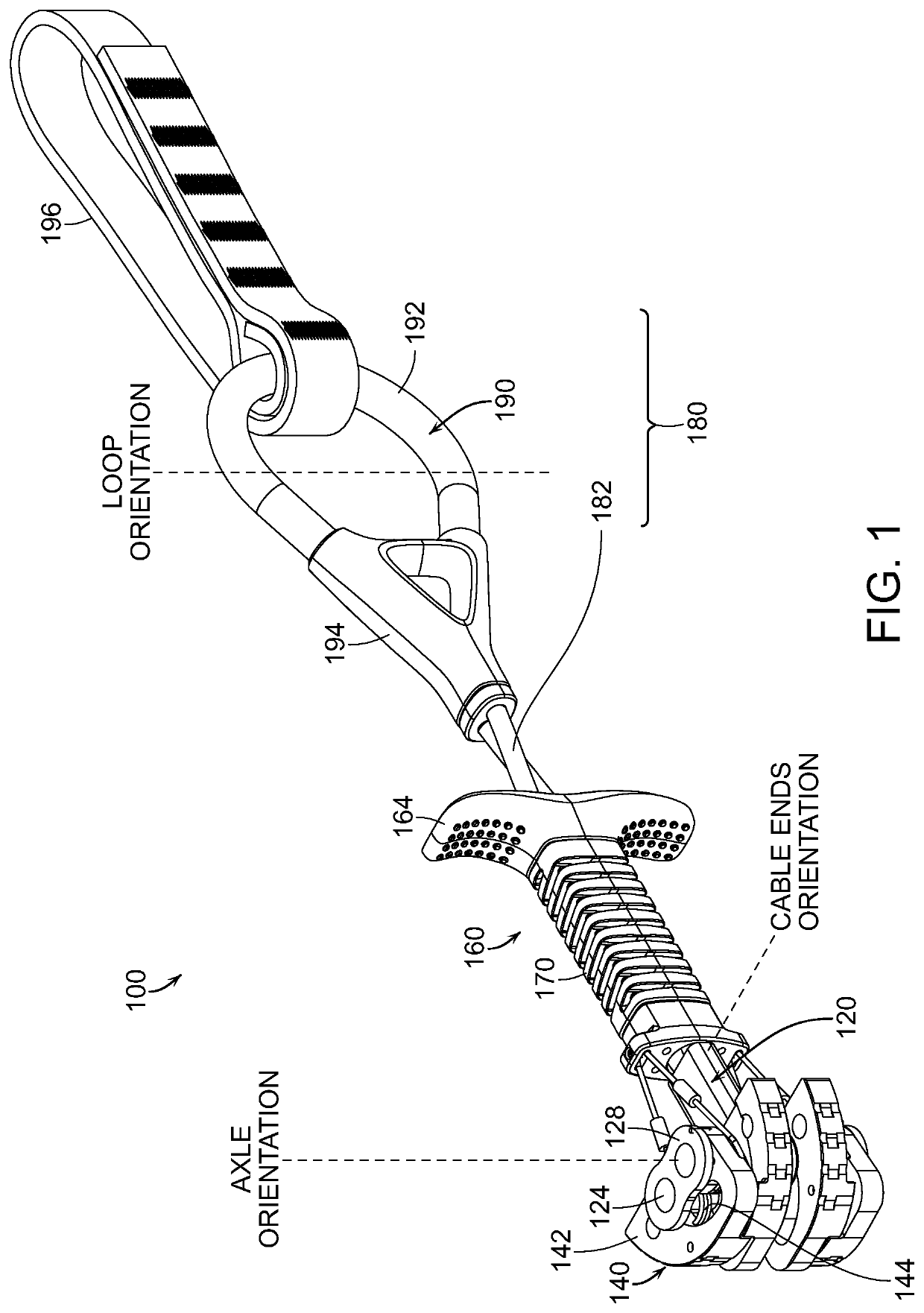
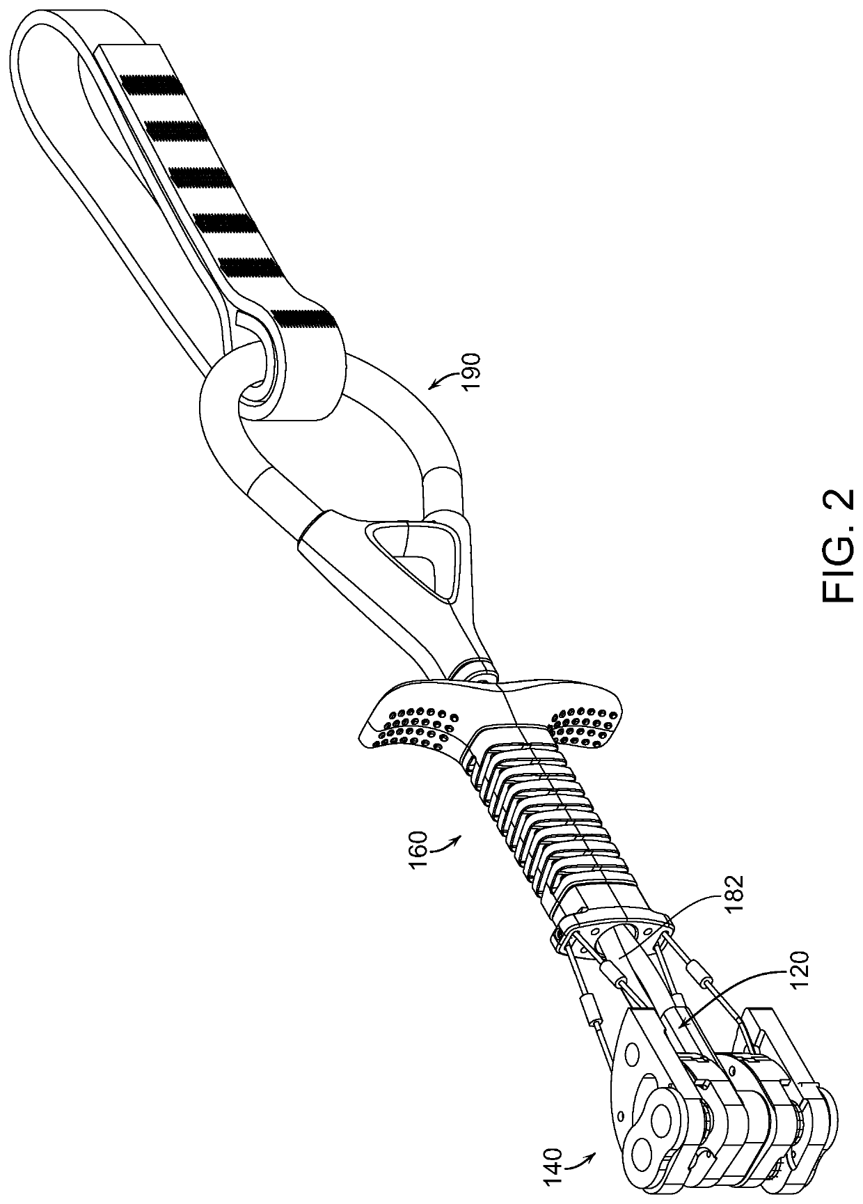
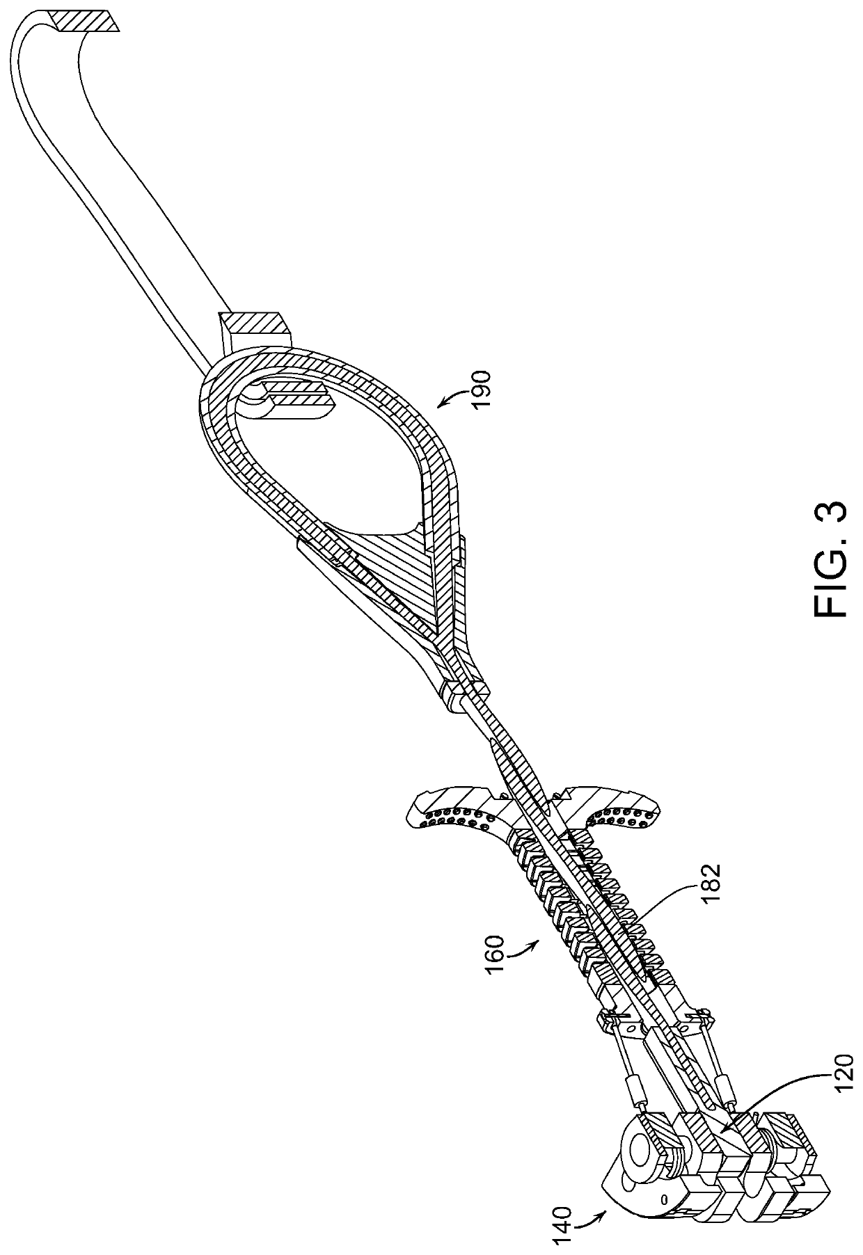
[0018]The present invention relates to active camming systems. One embodiment of the present invention relates to an improved camming stem system including a head member, a plurality of cam lobes, a connection system, and a retraction system. The cam lobes may be selectively rotatable between an extended state and a retracted state with respect to at least one axle of the head member. The connection system may create an elongated, substantially rigid region by intercoupling the head member with a loop. The connection system is configured to create an elongated, partially rigid region by intercoupling the head member with a loop, wherein the connection system comprises a twisted cable coupled between the head member and the loop, and wherein the loop is oriented substantially parallel to the at least one axle, and wherein the twisted cable includes a twisting radial angle of at least 90 degrees. The first and second end of the twisted cable may be coupled to the head member orthogona...


PUM


Abstract

One embodiment of the present invention relates to an improved camming stem system including a head member, a plurality of cam lobes, a connection system, and a retraction system. The cam lobes may be selectively rotatable between an extended state and a retracted state with respect to at least one axle of the head member. The connection system may create an elongated, substantially rigid region by intercoupling the head member with a loop. The connection system is configured to create an elongated partially rigid region by intercoupling the head member with a loop, wherein the connection system comprises a twisted cable coupled between the head member and the loop, and wherein the loop is oriented substantially parallel to the at least one axle, and wherein the twisted cable includes a twisting radial angle of at least 90 degrees.

Description

RELATED APPLICATIONS[0001]This application claims priority to U.S. provisional application Ser. No. 62 / 840,532 filed Apr. 30, 2019, the contents of which are incorporated by reference.FIELD OF THE INVENTION[0002]The invention generally relates to active camming systems. In particular, the present invention relates to an improved camming stem system.BACKGROUND OF THE INVENTION[0003]Climbers generally use clean protection devices for two distinct purposes. First, a clean protection device may be used as a form of safety protection for protecting a climber in the event of a fall, and second, a clean protection device may intentionally be used to artificially support a climber's weight. Clean protection devices cam or wedge into a crack, hole, gap, orifice, taper, or recess in order to support an outward force. The surface on which the clean protection device supports the outward force is considered the protection surface. The protection surface can consist of natural materials such as ...

Claims


Application Information

Patent Timeline
Patent Type & Authority Applications(United States)
IPC IPC(8): A63B29/02
CPCA63B29/02A63B29/024A63B2209/00
Inventor STECK, JEREMYHARMSEN, GARRETTBARGHAHN, BRENTHALL, JACOB
Owner BLACK DIAMOND EQUIPMENT
Why Eureka
Try Eureka