Method for calibrating an acoustic antenna

a technology of acoustic antenna and calibration method, which is applied in the field of acoustic antenna, can solve the problems of reducing the manufacturing cost, the gain and phase of the various transducers may exhibit substantial differences, and the imperfections of the various transducers

Active Publication Date: 2021-01-14
COMMISSARIAT A LENERGIE ATOMIQUE ET AUX ENERGIES ALTERNATIVES
View PDF0 Cites 1 Cited by
  • Summary
  • Abstract
  • Description
  • Claims
  • Application Information

AI Technical Summary

Benefits of technology

The invention is about an acoustic antenna that can detect and generate electrical signals from acoustic waves. The antenna has multiple transducers distributed over a row or plane, with a reference transducer in the middle. The antenna has a processing unit that can calibrate the signals from the transducers using a calibration acoustic source placed facing the antenna. The technical effect of this invention is to provide an improved and more accurate way to detect and measure acoustic waves.

Problems solved by technology

The technical problem addressed in this patent is the need for a simple and cost-effective calibration method for acoustic antennas that allows for individual correction of the gains and phases of each transducer, without requiring precise positioning of the calibration source.

Method used


Image

  • Method for calibrating an acoustic antenna
  • Method for calibrating an acoustic antenna
  • Method for calibrating an acoustic antenna

Examples


Embodiment Construction

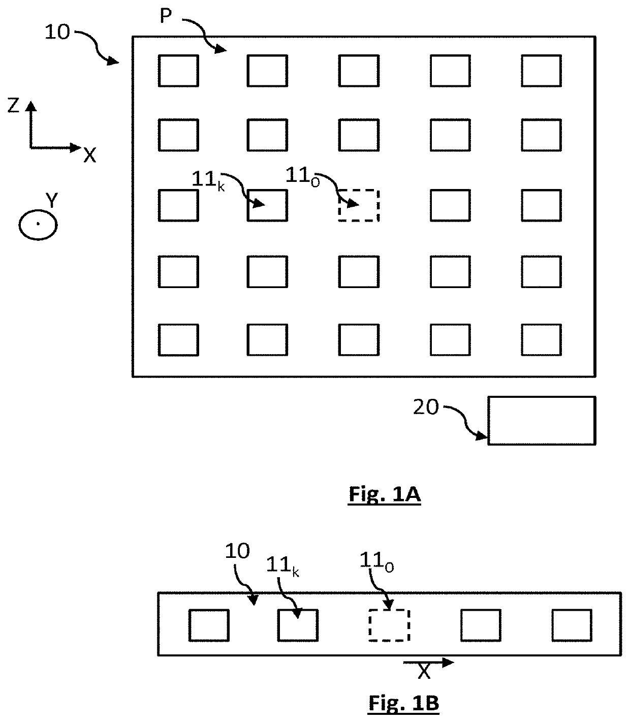
[0044]FIG. 1A shows a planar acoustic antenna 10. Such an antenna comprises elementary acoustic transducers 11k distributed over an antenna plane P. The elementary transducers are distributed over the antenna plane, about a reference transducer 110. The antenna plane P extends along a longitudinal axis X, defining rows, and along a lateral axis Z, defining columns. The antenna plane P is orthogonal to an axis Y. The longitudinal axis X and the lateral axis Z are secant, and preferably perpendicular to each other. The antenna 10 comprises a main axis Y0, perpendicular to the antenna plane P, and passing through the reference transducer 110.

[0045]The antenna 10 is connected to a processing unit 20, a processor or microprocessor for example. The processing unit 20 receives the signals generated by each transducer of the antenna, via a wired or wireless link. The processing unit is configured to execute certain steps of a calibration of the antenna, in particular when these steps requir...


PUM


Abstract

A method for calibrating an acoustic antenna (10), the acoustic antenna comprising a plurality of acoustic transducers (11k), each acoustic transducer being able to generate an electrical signal (sk) under the effect of a detection of an acoustic wave, the antenna comprising elementary transducers (11k) that are distributed over an antenna row or an antenna plane, about a reference transducer (110), the antenna defining a main axis (Y0), passing through the reference transducer, and perpendicular to the antenna row or antenna plane, the method comprising the following steps:
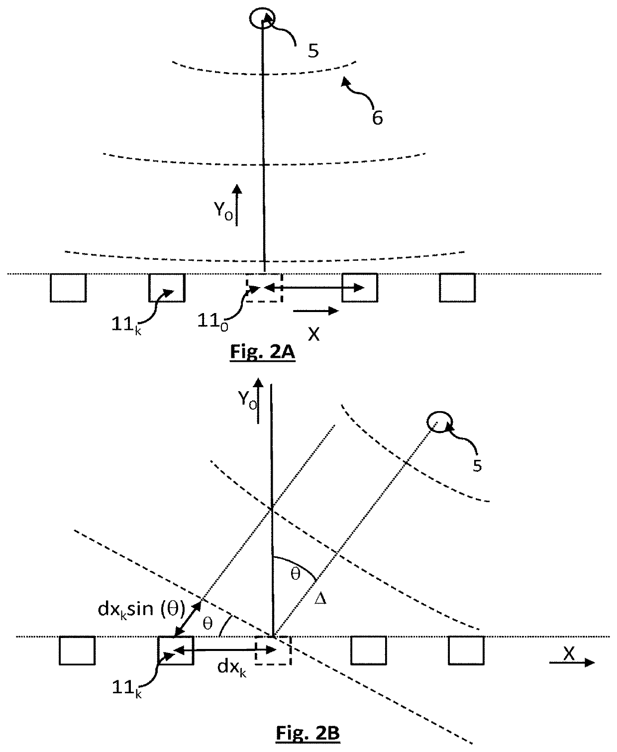
    • a) placing a calibration source (5) in at least one position (r0, rj) with respect to the antenna, the calibration source being able to transmit a calibration acoustic wave (6);
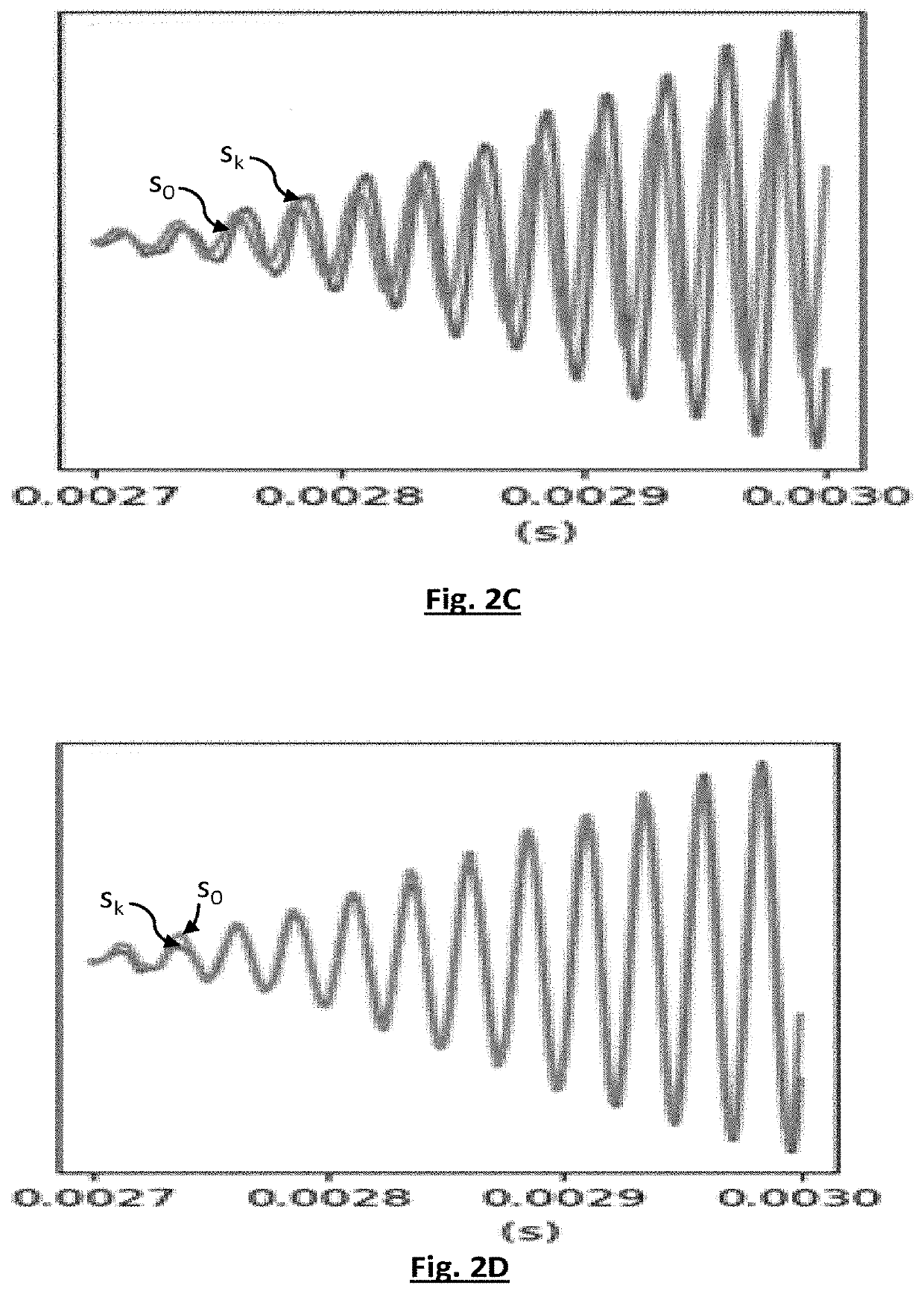
    • b) measuring signals (sk) generated by all or some of the elementary transducers in response to the calibration acoustic wave;
    • c) on the basis of the measurements performed in step b), determining a temporal phase shift (p0k,n, pk,j) of the signal respectively generated by each elementary transducer;
    • d) reiterating a) to c) in such a way that, in at least one iteration, the position of the calibration source may be considered to be centered on the main axis;
    • the method comprising estimating a phase shift (Φk) of each elementary transducer with respect to the reference transducer.

Description


Claims


Application Information

Patent Timeline
Owner COMMISSARIAT A LENERGIE ATOMIQUE ET AUX ENERGIES ALTERNATIVES
Why Eureka
Try Eureka