
Acetabular reamer handle and method of reaming an acetabulum

Pending Publication Date: 2021-01-21
DEPUY (IRELAND) LTD
View PDF2 Cites 2 Cited by
  • Summary
  • Abstract
  • Description
  • Claims
  • Application Information

AI Technical Summary

Benefits of technology

The invention is a reaming device for orthopedic surgery that allows the surgeon to better view the reaming process without having to remove the reamer and reamer handle from the acetabulum or disconnect the reamer handle from the reamer. This is achieved by tilting the shaft of the reamer relative to the longitudinal axis of the neck part, which typically allows a part of the acetabulum and / or reamer to be viewed. The locking mechanism prevents unwanted tilting of the shaft, and the engagement member is slideably mounted inside the hollow shaft to protect it from interference by fluids and bone fragments. The tilting of the shaft also makes it easier for the surgeon to work around soft tissue in the incision site.

Problems solved by technology

Visibility is generally rather limited during a hip replacement procedure.
For example, when using a reamer handle, it may be difficult for a surgeon to inspect the dome of the reamer while it is located in the acetabulum (e.g. for assessing the reaming depth).
In order to assess the reaming depth, the surgeon may remove the reamer handle and reamer from the incision site, or alternatively may detach the reamer handle from the reamer, so as to view the acetabulum and the reamer with the reamer still in-situ, but in either case this is inconvenient.

Method used


Image

  • Acetabular reamer handle and method of reaming an acetabulum
  • Acetabular reamer handle and method of reaming an acetabulum
  • Acetabular reamer handle and method of reaming an acetabulum

Examples


Embodiment Construction

[0061]Embodiments of the present invention are described in the following with reference to the accompanying drawings.

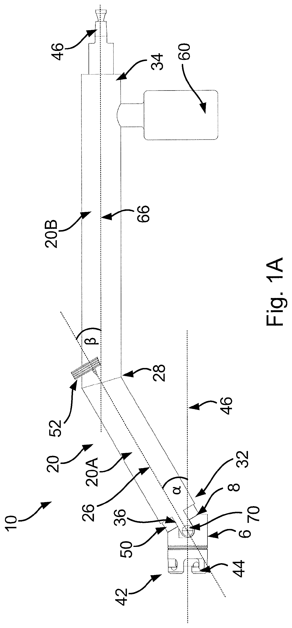
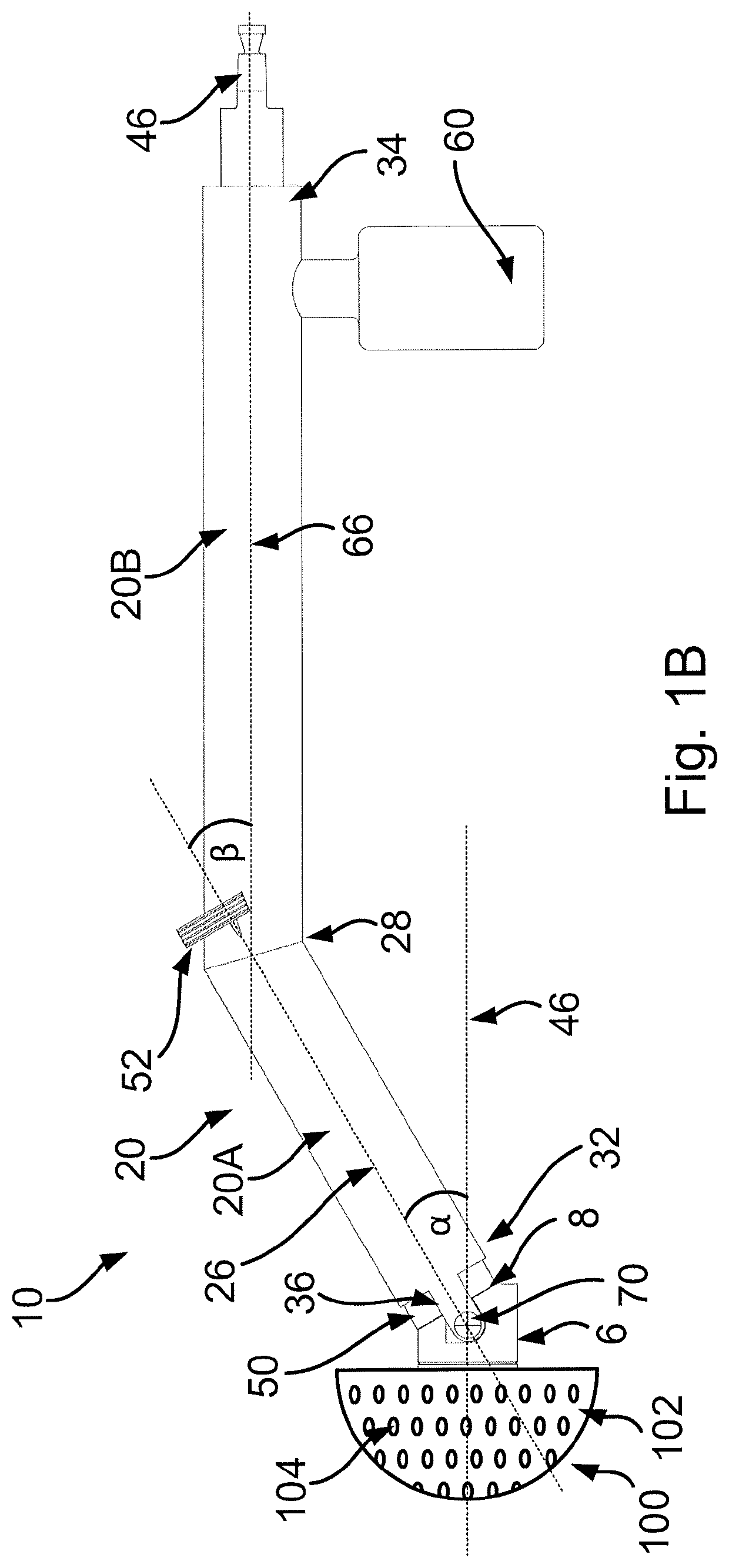
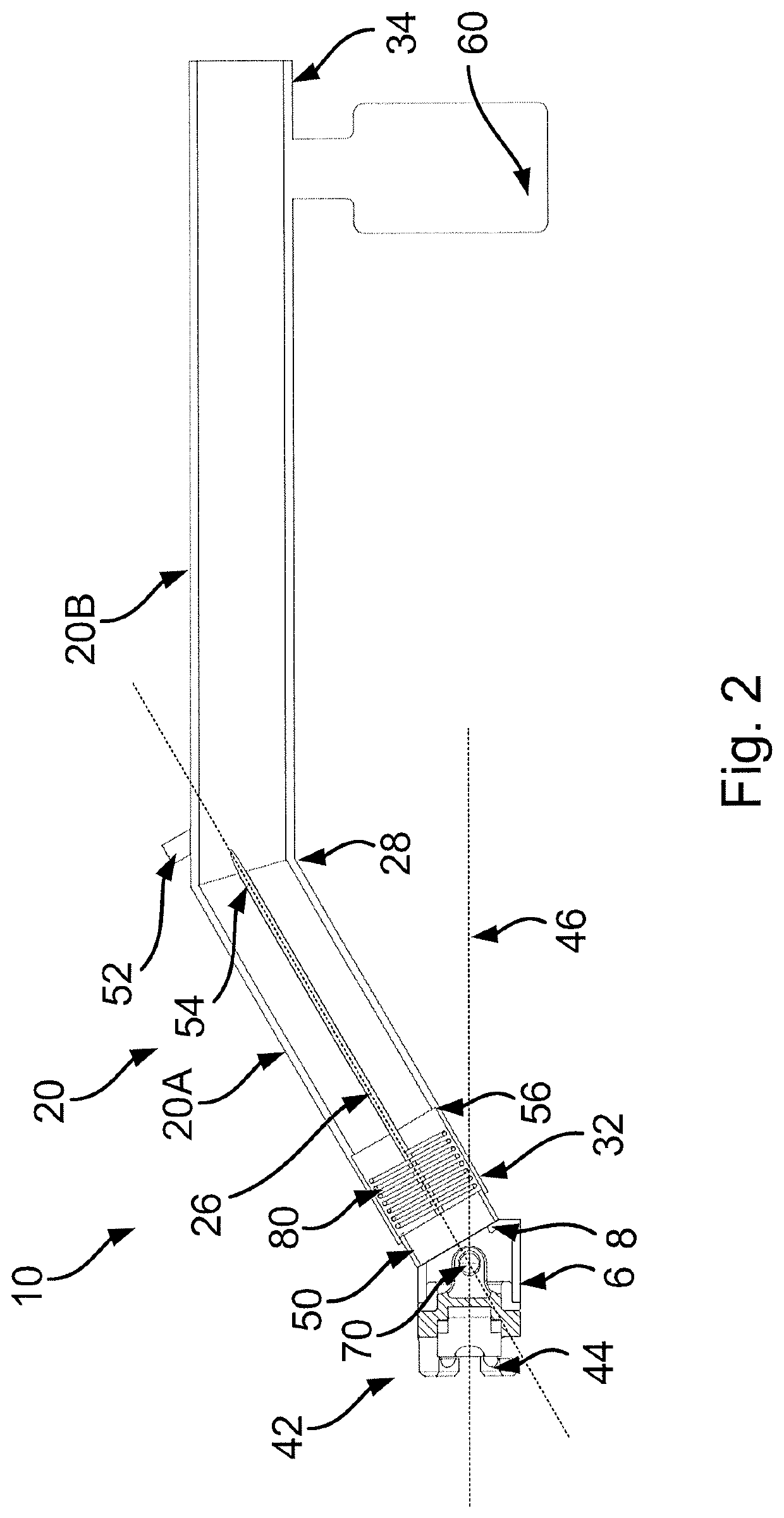
[0062]FIGS. 1 to 7 show various views of an acetabular reamer handle 10 according to an embodiment of this invention.

[0063]The acetabular reamer handle 10 includes a shaft 20. The shaft 20 has a proximal end 34 and a distal end 32. The shaft 20 is substantially hollow (see, for example, the cross section of FIG. 2).

[0064]In this embodiment, the shaft 20 includes a distal shaft section 20A and a proximal shaft section 20B. The shaft sections 20A, 20B are fixedly joined together at a bend 28 in the shaft 20, whereby a longitudinal axis 26 of the distal shaft section 20A is oriented at an angle β (see e.g. FIG. 1A) to a longitudinal axis 66 of the proximal shaft section 20B. Each shaft section 20A, 20B may have a distal end and a proximal end. In the present embodiment, the proximal end of the distal shaft section 20A is joined at the aforementioned bend 28 to the dista...


PUM


Abstract

An acetabular reamer handle including a shaft having a distal end, a neck part having a longitudinal axis, a driveline extending through the shaft and the neck part, and a locking mechanism. A distally located head part of the driveline is mounted for rotation about the longitudinal axis of the neck part and is connectable to a reamer. The distal end of the shaft and a proximal end of the neck part are pivotally attached to allow the shaft to be tilted relative to the longitudinal axis. The tilting can allow part of the acetabulum and / or reamer that is otherwise obscured to be viewed. The locking mechanism includes an engagement member having an engagement surface located at the distal end of the shaft. The engagement member is moveable distally to urge the engagement surface against the proximal end of the neck part.

Description

FIELD OF THE INVENTION[0001]This invention relates to an acetabular reamer handle. This invention also relates to a method of reaming an acetabulum in a hip replacement procedure.BACKGROUND OF THE INVENTION[0002]Hip replacement is a surgical procedure in which the hip joint is replaced by a prosthetic implant. As part of a hip replacement procedure, an acetabulum of the patient may be prepared for receiving an acetabular cup implant by reaming it to an appropriate size and depth. A surgical tool for reaming the acetabulum may include a reamer having a substantially hemispherical dome to be received in the acetabulum. The reamer may also include features located on an outer surface of the dome for grating the inner surface of the acetabulum as the reamer rotates. The reamer may be attached to a distal end of a tubular reamer handle, to allow the surgeon to manipulate it (e.g. to position the dome within the acetabulum and to apply a force for pressing the reamer against the inner sur...

Claims


Application Information

Patent Timeline
IPC IPC(8): A61B17/16
CPCA61B17/1666A61B17/1631
Inventor FLATTERS, IANHORNE, DAVIDTEMPLE, DUNCAN
Owner DEPUY (IRELAND) LTD
Learn More