
Charging and discharging control device

a control device and double-layer capacitor technology, applied in the direction of capacitor propulsion, safety/protection circuit, emergency power supply arrangement, etc., can solve the problems of cost increase and size increase, and achieve the effect of cost reduction and size reduction

Inactive Publication Date: 2021-01-28
YAZAKI CORP
View PDF0 Cites 0 Cited by
  • Summary
  • Abstract
  • Description
  • Claims
  • Application Information

AI Technical Summary

Benefits of technology

The patent text describes a charging and discharging control device for an electric double-layer capacitor that can achieve cost and size reduction. In one aspect, the device controls the charging and discharging of the capacitor based on the ambient temperature. If the temperature is too low, the device causes the capacitor to generate heat, preventing a decrease in capacitance and reducing the need for more capacitors. Additionally, a discharging resistor can be added to further heat the capacitor and prevent further decrease in capacitance. Overall, the device allows for efficient use of the electric double-layer capacitor, reducing costs and size.

Problems solved by technology

For example, a capacitance of an EDLC is reduced by 30% in a low-temperature environment of −40° C., compared with a capacitance in a room-temperature environment of 25° C. Only seven EDLCs are required at normal temperature, but 10 EDLCs are necessary in consideration of a low temperature environment, resulting in a cost increase and a size increase.

Method used


Image

  • Charging and discharging control device
  • Charging and discharging control device

Examples


first embodiment

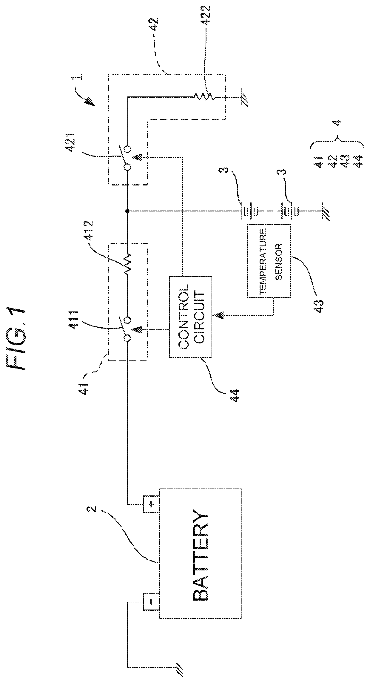
[0017]A power supply system 1 of a first embodiment is mounted on an automobile. As shown in FIG. 1, the power supply system 1 includes an in-vehicle battery 2 as an external power supply, an electric double-layer capacitor (EDLC) 3, and a charging and discharging control device 4 that controls charging and discharging of the EDLC 3. The in-vehicle battery 2 includes a secondary battery charged by an alternator (not shown) or the like.

[0018]A plurality of EDLCs 3 are connected in series to obtain a large capacitance. The EDLC 3 is mounted on a vehicle for applications such as a backup power supply for the in-vehicle battery 2, an energy supply during start of an engine of an idling stop system, energy regeneration during braking of brake, and power assist.

[0019]The charging and discharging control device 4 includes a charging circuit 41 for charging the EDLC 3, a discharging circuit 42 for discharging the EDLC 3, a temperature sensor 43 for detecting an ambient temperature of the ED...

second embodiment

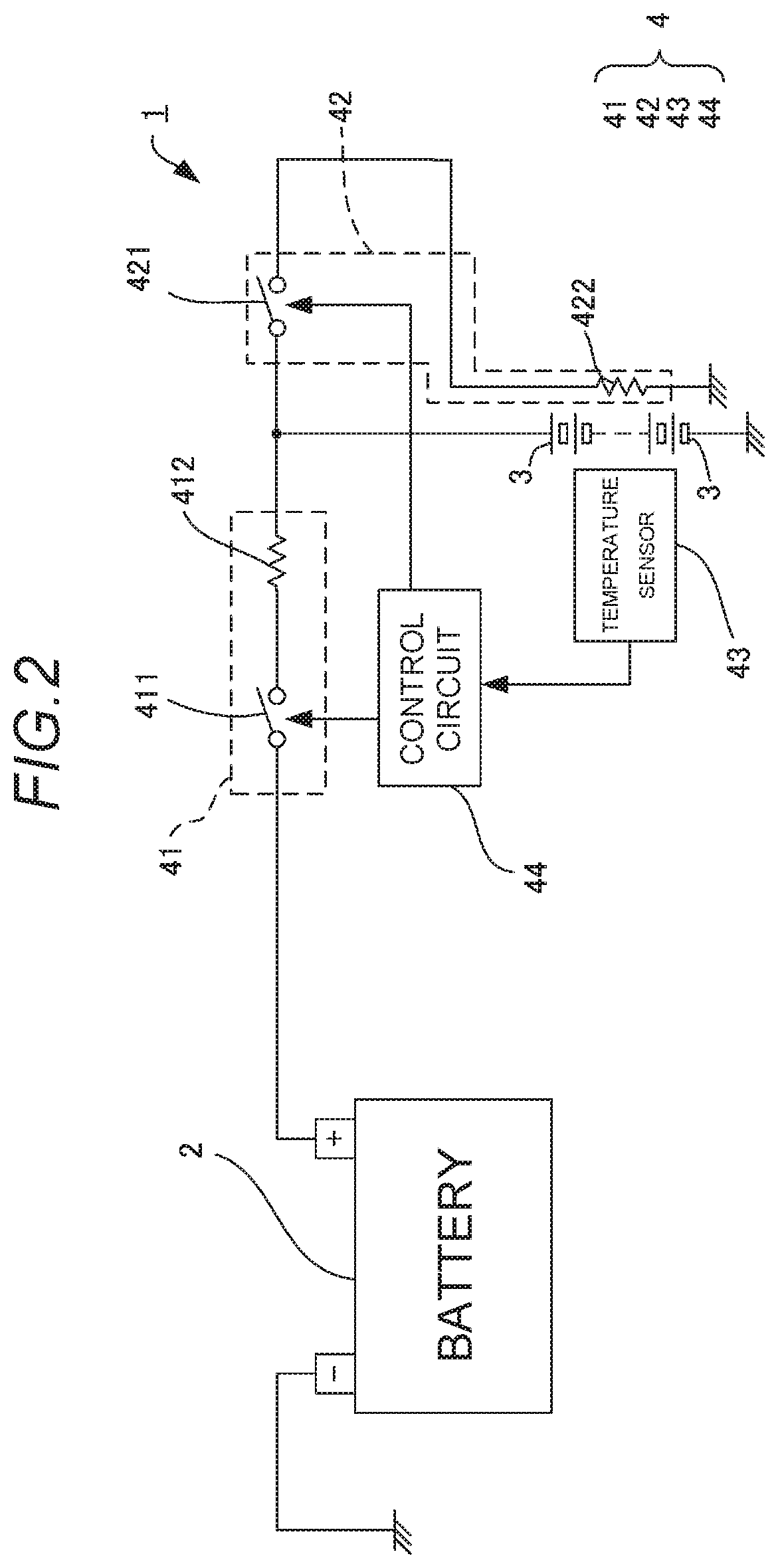
[0025]Next, a power supply system 1 according to a second embodiment will be described with reference to FIG. 2. In FIG. 2, the same parts as those in FIG. 1 already described in the first embodiment are denoted by the same reference numerals, and detailed descriptions thereof will be omitted.

[0026]The first embodiment and the second embodiment are largely different from each other in an arrangement position of the discharging resistor 422. In the second embodiment, the discharging resistor 422 is disposed in a vicinity of the EDLC 3. As a result, when a discharging current from the EDLC 3 flows through the discharging resistor 422, the discharging resistor 422 generates heat. The EDLC 3 can be heated by the heat generated in the discharging resistor 422, and the decrease of the capacitance of the EDLC 3 at a low temperature can be further prevented.

[0027]Here, the features of the embodiments of the charging and discharging control device according to the present invention will be b...


PUM


Abstract

A charging and discharging control device of an electric double-layer capacitor, the charging and discharging control device includes a charging circuit receiving power supply from an external power supply and charging the electric double-layer capacitor, a discharging circuit discharging the electric double-layer capacitor, and a control circuit controlling the charging circuit and the discharging circuit to alternately repeat the charge and the discharge of the electric double-layer capacitor when temperature of the electric double-layer capacitor is equal to or lower than a predetermined value.

Description

CROSS REFERENCE TO RELATED APPLICATIONS[0001]This application claims priority from Japanese Patent Application No. 2019436347 filed on Jul. 24, 2019 and Japanese Patent Application No. 2020-48379 filed on Mar. 18, 2020, the entire contents of which are incorporated herein by reference.BACKGROUND OF THE INVENTIONField of the Invention[0002]The present invention relates to a charging and discharging control device for an electric double-layer capacitor.Description of Related Art[0003]Patent Literature 1 (JP-A-2015-231269) has proposed an electric double-layer capacitor (EDLC) with a large capacitance is mounted on an automobile depending on requests for miniaturization, endurance improvement, life, and instantaneous load current supply of an automobile battery. The EDLC is used for a backup power supply, or is used for a drive source of an electric motor and a cell motor, and recovery of regenerative energy, similarly to a normal battery.[0004]Since only one EDLC cannot meet a large c...

Claims


Application Information

Patent Timeline
IPC IPC(8): H02J7/34H02J7/00
CPCH02J7/345H02J9/06H02J2207/50H02J7/007194H01G11/14H01G11/18H02J7/0068H02J7/0069B60L3/0046B60L50/40B60L58/25B60L58/27F02N11/0862F02N2011/0885H02J7/0029Y02E60/13Y02T10/70
Inventor WATARU, KAZUHISAIWASAKI, KATSUYUKI
Owner YAZAKI CORP
Learn More