A Method for Implementing Beam Hopping in a Satellite Communications Network

a satellite communications network and beam hopping technology, applied in the field of communication, can solve the problems of increasing delay and jitter, limited satellite's field of view, and limited number of concurrent receive and transmit signals,

Inactive Publication Date: 2021-02-04
SATIXFY ISRAEL LTD
View PDF0 Cites 3 Cited by
  • Summary
  • Abstract
  • Description
  • Claims
  • Application Information

AI Technical Summary

Benefits of technology

[0026]It is another object of the present disclosure to provide a...

Problems solved by technology

Furthermore, because of it circles the earth at a relatively low altitude, the satellite's field of view is limited to a few thousand km at the most.
At the same time, the number of concurrent receive and transmit si...

Method used


Image

  • A Method for Implementing Beam Hopping in a Satellite Communications Network
  • A Method for Implementing Beam Hopping in a Satellite Communications Network
  • A Method for Implementing Beam Hopping in a Satellite Communications Network

Examples


example i (fig.6a)

Example I (FIG. 6A)

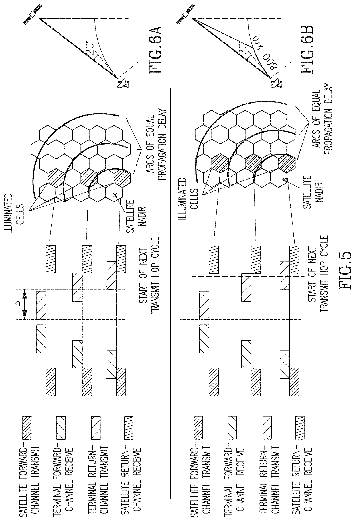
[0073]Maximal propagation delay range 8.3-16.9 mS (say 8.6 msec)[0074](space-earth-space, 1250 km inclined orbit, nadir to 20° elevation angle)[0075]For an 8-cell cycle, dwell time must be at least 1.4 msec[0076]For the entire cycle—at least 11.4 msec to accommodate the worst-case delay range.

example ii (fig.6b)

Example II (FIG. 6B)

[0077]For a more limited (contiguous) geographical extent of hopping beams:

Beam diameter400kmLimit on downrange distance800kmMaximal differential delay4.7msec(worst-case is towards edge of coverage)Minimal dwell time0.78msec(8-cell cycle)Minimal hopping cycle duration6.2msec(8-cell cycle)

Options for Hopping Cycle-Time Reduction

[0078](i) For sparse coverage, cycle time may be reduced by implementing a progressive shifting of the phase between the transmit and receive cycles as a function of the distance of the cell group (cycle) from the satellite nadir. (FIG. 7).[0079](ii)Misaligning forward- and return-channel beams through one or both of:[0080]Grid offset (FIG. 8).[0081]Different transmit and receive beam diameters.[0082]In FIG. 8, the orange return channel beam serves terminals from three forward channel beams (red, green and blue). If, for example, the return channel controller prioritizes assigning to a terminal in the red beam time slots that are inaccessib...


PUM


Abstract

A method is provided for conveying communications within a satellite communication network, by implementing a beam hopping technique for communicating with half-duplex user terminals.

Description

FIELD OF THE DISCLOSURE[0001]The present disclosure relates to the field of communications and in particularly to communications exchanged between satellite and terrestrial communication terminals / gateways.BACKGROUND OF THE DISCLSOURE[0002]Communication satellites in Low Earth Orbit (LEO), circle the earth at a relatively low altitude from 500 to 1500 km. At these altitudes, the orbital period is in the order of 90 to 120 minutes and a satellite is only visible from any location on the ground for just a small period of the time. Furthermore, because of it circles the earth at a relatively low altitude, the satellite's field of view is limited to a few thousand km at the most. For both these reasons, several LEO satellites—a constellation—are used in order to provide continuous communication coverage over a large area. In a typical constellation, several LEO satellites (e.g. 10) are placed at the same orbit at equal distances from each other. Additionally, similar groups of satellite...

Claims


Application Information

Patent Timeline
IPC IPC(8): H04B7/185H04B7/204H04L5/16
CPCH04B7/18517H04B7/18541H04L5/16H04B7/2041H04B7/212H04B7/1851H04L5/0023
Inventor KESHET, ARIERAINISH, DORON
Owner SATIXFY ISRAEL LTD
Why Eureka
Try Eureka