Control device and steering device

Active Publication Date: 2021-02-11
JTEKT CORP
View PDF0 Cites 3 Cited by
  • Summary
  • Abstract
  • Description
  • Claims
  • Application Information

AI Technical Summary

Benefits of technology

[0004]The control on the toe angle according to the related art is performed for the purpose of improving the fuel efficiency during straight travel

Problems solved by technology

The control on the toe angle according to the related art is performed for the purpose of improving the fuel efficiency during straight travel an

Method used


Image

  • Control device and steering device
  • Control device and steering device
  • Control device and steering device

Examples


Example

[0016]A control device and a steering device according to an embodiment of the present disclosure will be described below with reference to the drawings. The numerical values, shapes, materials, constituent elements, positional relationship among the constituent elements, state of connection, steps, order of the steps, etc. are exemplary, and are not intended to limit the present disclosure. A plurality of disclosures may be described in relation to one embodiment below. Constituent elements not described in a claim are described as optional for the disclosure according to the claim. The drawings are schematic diagrams that include exaggeration, omission, and scale adjustment as appropriate, in order to illustrate the present disclosure, and may be different from the actual shapes, positional relationship, or scale.

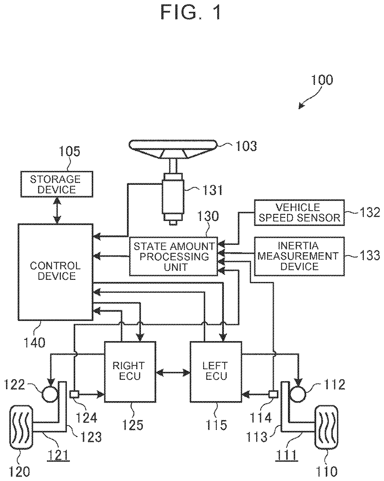
[0017]First, the overall configuration of a steering device 100 for a vehicle 101 according to the embodiment of the present disclosure will be described. FIG. 1 is a blo...


PUM


Abstract

A control device includes an electronic control unit. The electronic control unit determines a right steering command value and a left steering command value. The electronic control unit acquires path information indicating a target path for the vehicle. The electronic control unit corrects a steering command value such that the vehicle travels along the target path. The electronic control unit corrects the right steering command value and the left steering command value so as to bring the distribution ratio between a skid angle of a right steered wheel and a skid angle of a left steered wheel to a target distribution ratio.

Description

CROSS-REFERENCE TO RELATED APPLICATION[0001]This application claims priority to Japanese Patent Application No. 2019-146922 filed on Aug. 9, 2019, incorporated herein by reference in its entirety.BACKGROUND1. Technical Field[0002]The present disclosure relates to a control device that independently steers steered wheels disposed on the right and left sides, and to a steering device.2. Description of Related Art[0003]In some steering devices for vehicles, a steering wheel and a steering operation mechanism are not mechanically connected to each other, and the steered angles of steered wheels are controlled independently. Japanese Unexamined Patent Application Publication No. 2013-184619 (JP 2013-184619 A), for example, describes a technique of computing right and left target tire lateral forces that minimize the total sum of tire lateral forces in order to reduce the travel resistance during straight travel, and controlling the toe angle such that the actual tire lateral forces obtai...

Claims


Application Information

Patent Timeline
IPC IPC(8): B62D6/00B62D5/04
CPCB62D6/002B62D5/0418B62D6/00B62D5/04B62D15/025B60W30/045B60W30/18145
Inventor MIURA, YUICHIKOJIMA, TAKASHIKARIATSUMARI, YUJI
Owner JTEKT CORP
Why Eureka
Try Eureka