Eureka AIR delivers breakthrough ideas for toughest innovation challenges, trusted by R&D personnel around the world.

Vortex acceleration wind energy tower

a wind energy tower and acceleration technology, applied in the direction of renewable energy generation, machine/engine, greenhouse gas reduction, etc., can solve the problems of unpopularity in populated areas, all are very visible, etc., and achieve the effect of 100% clean energy recovery and high power production

Active Publication Date: 2021-02-11
MIZERIT BRANKO
View PDF0 Cites 1 Cited by
  • Summary
  • Abstract
  • Description
  • Claims
  • Application Information

AI Technical Summary

Benefits of technology

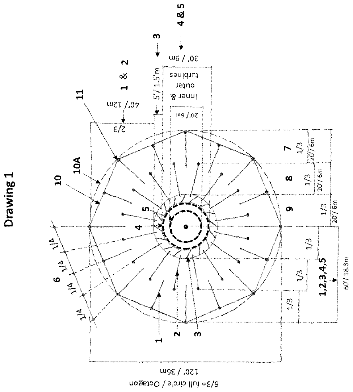
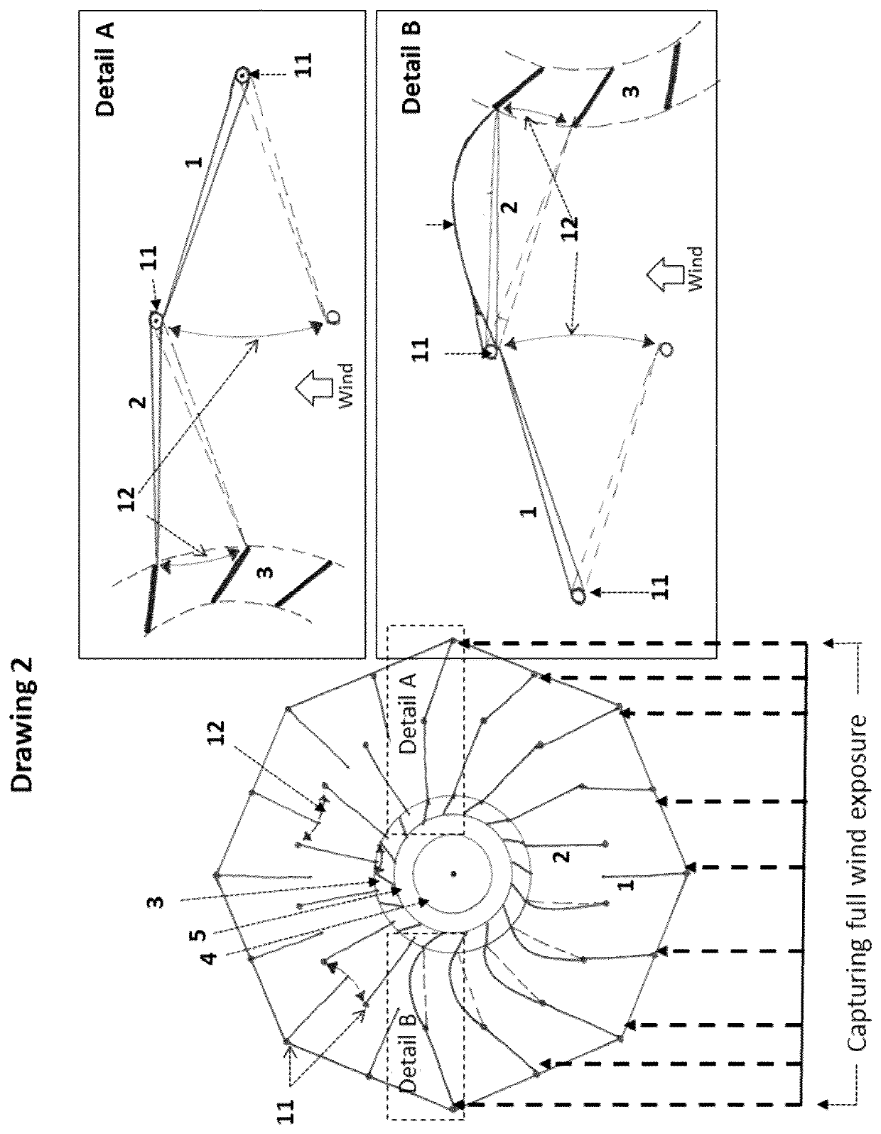
The present invention provides a Complicated, Interactive, Vortex Acceleration Recovery (CIVAR) Energy Tower, which is designed to generate clean energy to meet the building's energy requirements. The tower uses wind, solar, and geothermal sources, and waste incineration heat to convert them into clean energy. The tower has multiple levels of wind intakes that interact with the central vortex in a vertically compounding way. The rotation of the vortex wind force is accelerated and multiplied by the positive and negative forces of the wind. The tower is visually attractive and people-friendly because there is no wind generating equipment visible from outside or inside.

Problems solved by technology

Traditionally, wind generating equipment forms either part of a tall tower or is installed on top of buildings and other structures, but all are very visible and unpopular in populated areas.

Method used


Image

  • Vortex acceleration wind energy tower
  • Vortex acceleration wind energy tower
  • Vortex acceleration wind energy tower

Examples


Embodiment Construction

[0037]The technology wording used herein is for the purpose of describing specific embodiments, not intended to be limiting to the invention. The terms “and / or” includes all combination of one or more of listed items. The singular words “a”, “an”, and “the” are intended to include singular and plural forms. The terms “comprises, comprising”, “represents, representing”, “consist of, consisting” specify the presence of stated features, operations, elements and components, but do not exclude the presence of other features, operations, elements, components and groups thereof. It is clarified that by describing the CIVAR Vertical Tower invention, a number of processes and functions are disclosed. Each has individual benefit and each can be used in conjunction with one, more or all of the other disclosed features, operations or components. The phrase “CIVAR Energy Tower”, representing the present CIVAR Energy Tower invention and plurality thereof, is hereinafter used by the full said phra...


PUM


Abstract

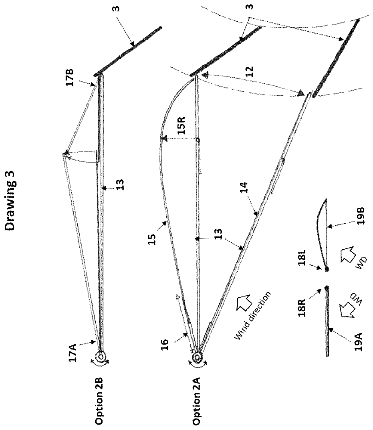
An energy-harvesting building structure has multiple levels, a vertical shaft (central vortex tower] to direct wind upward toward an outlet at the top, and multiple wind powered turbines in the shaft. Wind collection areas on multiple levels are exposed to multiple directions. Wind vanes pivot into a backstopped position for redirecting wind to spiral inward toward the shaft. Wind twisters receive and further redirect wind inward and upward into the shaft to feed an air vortex driving the turbines at different levels. Two concentric stages of wind vanes may be included within wind collection areas, with the inner stage vanes having a surface which deforms in one direction but not the other. The building can include occupancy zones between wind collection levels. Heated air can be released into the bottom of the shaft to feed the vortex. At a top level, another wind turbine can draw wind up the shaft.

Description

FIELD OF INVENTION[0001]The present invention relates to energy harvesting structures in general and in particular to building structures which harvest and utilize wind, solar, geothermal and incineration energy.BACKGROUNDPower Generating Windmills & Turbines[0002]Over the years, oil, coal and other gas reserves used for industries producing energy and power, have been diminishing worldwide. While creating major pollution in the air, as well as our land and water supplies, these industries have become a major target for criticism by leading scientists and the public. Clean, pollution free, renewable energy projects have become the main focus of future energy production. Many concepts have been designed and built and new ones are being patented and tested every year. Among solar panels, wave, tide and many other types of power generating systems, wind based designs and turbine generators have had a major impact on today's planning for our present and future power plants. There are va...

Claims


Application Information

Patent Timeline
Patent Type & Authority Applications(United States)
IPC IPC(8): F03D9/39F03D3/00
CPCF03D9/39F03D3/0427F03D3/005Y02B10/30Y02E10/74Y02E10/728F05B2240/131F05B2240/211F05B2240/132F03D3/0418
Inventor MIZERIT, BRANKO
Owner MIZERIT BRANKO
Why Eureka
Eureka Blog
Learn More