
Fuel cell unit

Active Publication Date: 2021-02-11
TOYOTA JIDOSHA KK
View PDF0 Cites 3 Cited by
  • Summary
  • Abstract
  • Description
  • Claims
  • Application Information

AI Technical Summary

Benefits of technology

The present invention provides a fuel cell unit where the case that holds the fuel cell stack and the case that holds the power converter can easily be fixed to each other while also preventing heat from transferring between them.

Problems solved by technology

The case which houses the fuel cell stack and the case which houses the power converter are occasionally different in size, and it may be difficult to fix the two cases to each other.
When the two cases are fixed to each other, heat of the fuel cell stack may be conducted to the power converter via the opening portions, which may affect electronic parts of the power converter.
In addition, heat of the power converter may be conducted to the fuel cell stack, which may dry the inside of the fuel cell stack and affect power generation performance.

Method used


Image

  • Fuel cell unit
  • Fuel cell unit
  • Fuel cell unit

Examples


first modification

[0075]Next, a fuel cell unit 1a according to a first modification will be described. Components that are the same as or similar to those according to the present embodiment are given the same or similar reference numerals to omit description thereof. FIG. 4 is a perspective view illustrating the appearance of a fuel cell unit 1a according to a first modification. FIG. 5 is an exploded perspective view of the fuel cell unit 1a according to the first modification. FIG. 6 illustrates the inside of the fuel cell unit 1a according to the first modification as seen from the upper side. FIG. 7 is a sectional view taken along the line VII-VII in FIG. 6.

Schematic Configuration of Fuel Cell Unit 1a

[0076]The fuel cell unit 1a includes stack cases 10a and 10b, fuel cell stacks 100a and 100b housed in the stack cases 10a and 10b, respectively, a converter case 50a, a step-up converter 500a housed in the converter case 50a, and an adapter 70a. The stack cases 10a and 10b are the same as the stac...

second modification

[0090]Next, a fuel cell unit 1b according to a second modification will be described. FIG. 9 is a sectional view of the fuel cell unit 1b according to the second modification. FIG. 9 corresponds to FIG. 7. In FIG. 9, a step-up converter 500b is illustrated in a simplified manner by the dashed lines, and stack cases 10ab and 10bb are not given some reference numerals to omit description. The stack cases 10ab and 10bb are respectively different in shape from the stack cases 10a and 10b discussed above, and the flange portions thereof are also different in shape from the flange portions 18 discussed above. Such differences will be discussed in detail later. The stacking direction of unit cells of fuel cell stacks 100ab and 100bb housed in the stack cases 10ab and 10bb, respectively, is the X direction as in the present embodiment and the first modification. FIG. 10 illustrates an adapter 70b as seen from above. In FIG. 10, opening portions 15ab of respective upper wall portions 15b of ...


PUM


Abstract

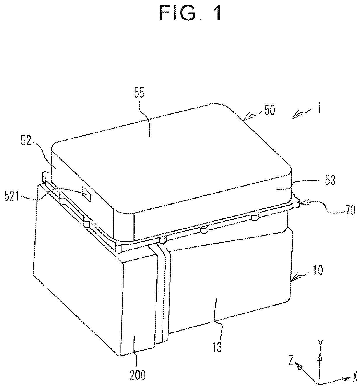
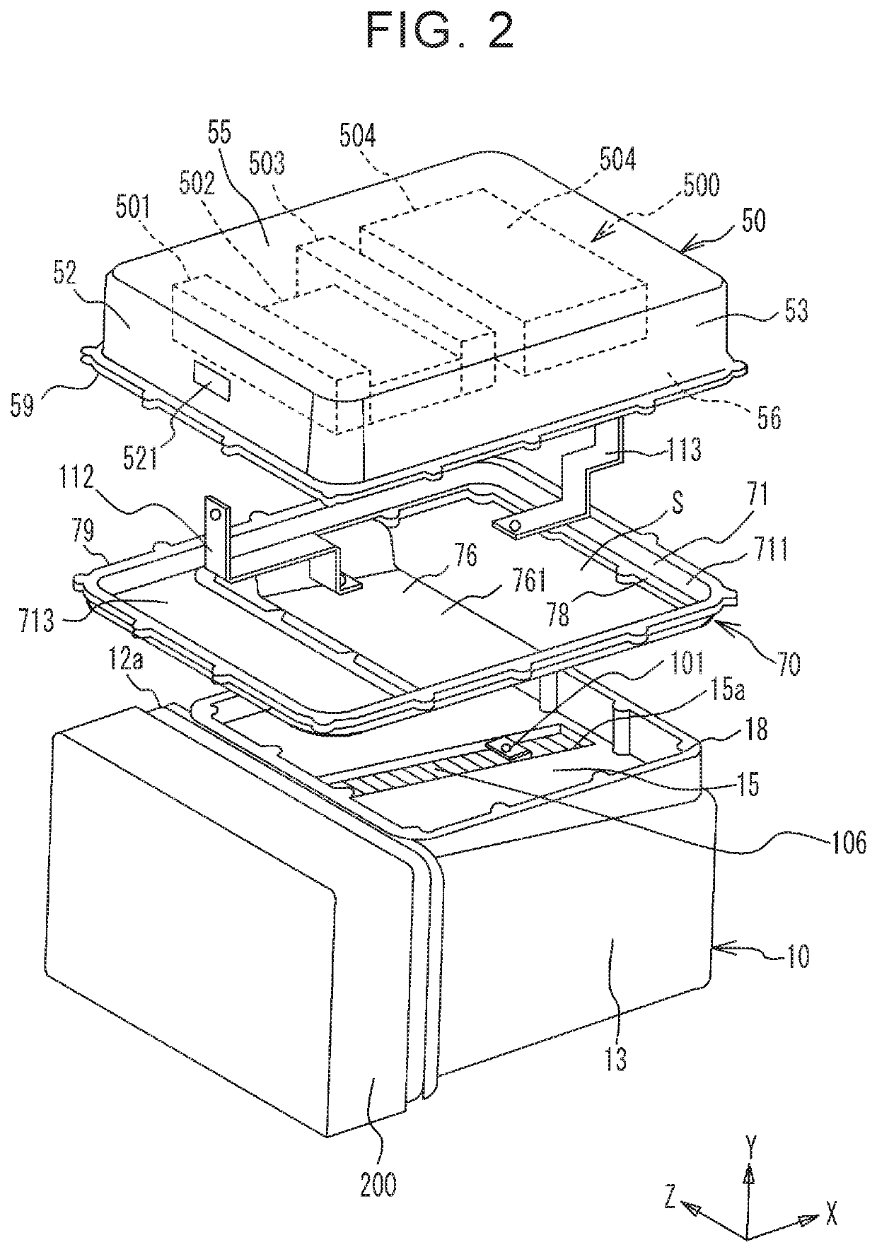
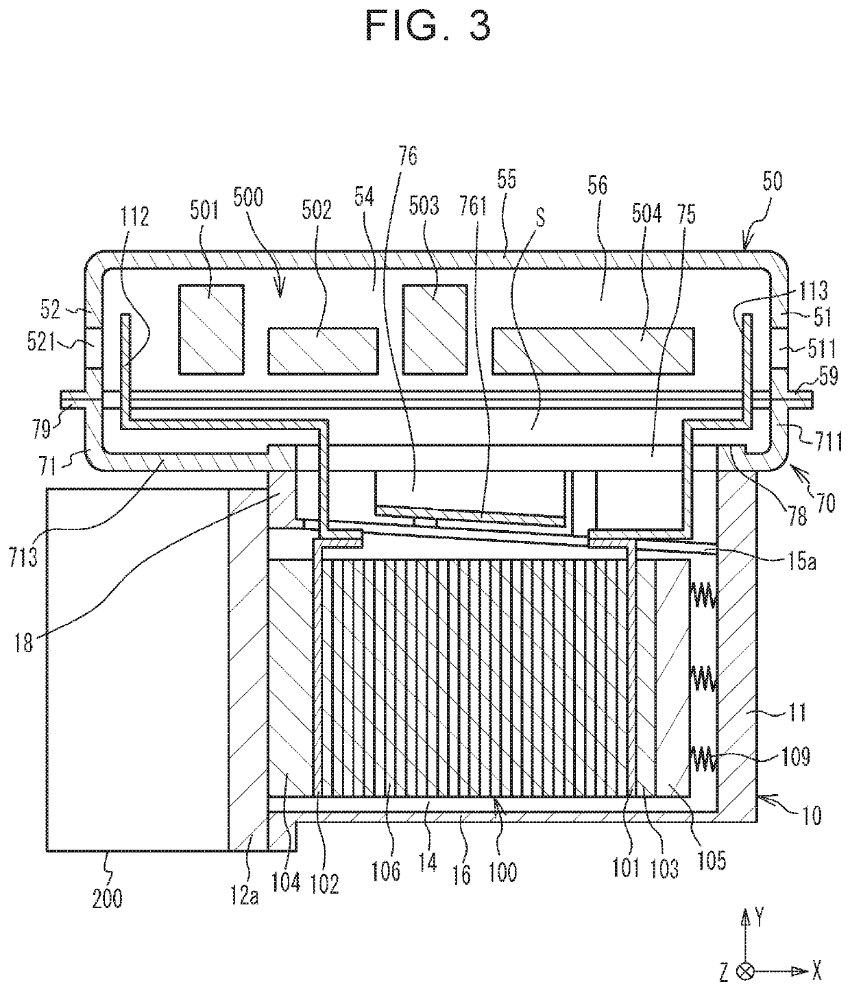
A fuel cell unit includes: a first case housing a fuel cell stack; a second case housing a power converter; an adapter fixing the first and second cases together; and a conductive member connecting between the fuel cell stack and the power converter. A first flange portion, surrounding a first opening portion, of the first case and a second flange portion, surrounding a second opening portion, of the second case are different in at least one of shape and size. The adapter includes: a third flange portion corresponding to the first flange portion; a fourth flange portion corresponding to the second flange portion; a surrounding wall portion continuous from the third flange portion to the fourth flange portion to define an internal space communicating with openings inside the third and fourth flange portions; and a partition wall portion between the first opening portion and the second opening portion.

Description

INCORPORATION BY REFERENCE[0001]The disclosure of Japanese Patent Application No. 2019-144707 filed on Aug. 6, 2019 including the specification, drawings and abstract is incorporated herein by reference in its entirety.BACKGROUND1. Technical Field[0002]The present disclosure relates to a fuel cell unit.2. Description of Related Art[0003]To unitize a fuel cell stack and a power converter that converts power of the fuel cell stack, a case that houses the power converter is occasionally fixed to a case that houses the fuel cell stack while electrically connecting between the fuel cell stack and the power converter (see Japanese Patent Application Publication No. 2017-073199 (JP 2017-073199 A), for example).SUMMARY[0004]The case which houses the fuel cell stack and the case which houses the power converter are occasionally different in size, and it may be difficult to fix the two cases to each other.[0005]In addition, it is necessary to provide the two cases with opening portions that a...

Claims


Application Information

Patent Timeline
IPC IPC(8): H01M8/2475H01M8/249H01M8/04082
CPCH01M8/2475H01M8/04201H01M8/249H01M8/04067H02M1/00H01M2250/20Y02E60/50
Inventor ITOU, MASAYUKIKINOSHITA, KEITA
Owner TOYOTA JIDOSHA KK
Learn More