Method for manufacturing rolled retraction cord

a technology of retraction cord and manufacturing method, which is applied in the field of rolled retraction cord manufacturing, can solve the problems of limited deformability, gingival bleeding, and often occurring gingival bleeding, and achieve the effects of increasing plasticity, easy torn or shredded, and poor deformability

Pending Publication Date: 2021-03-04
CHANG FU LONG
View PDF0 Cites 0 Cited by
  • Summary
  • Abstract
  • Description
  • Claims
  • Application Information

AI Technical Summary

Benefits of technology

[0005]In view of the drawbacks that the firm retraction cords have poor deformability, the knitted retraction cord is easily torn or shredded, and these conventional retraction cords cause gingival bleeding or tissue trauma and even permanent damage such as the gingival recession and degeneration, the objective of the present invention is to provide a rolled detraction cord with a smooth surface formed by a non-firm, non-knitted pattern to increase the plasticity, enhance ductility, and reduce gingival bleeding, ensuring that the teeth impression or other treatment can be carried out smoothly while reducing the patient's discomfort.
[0017]The rolled retraction cord of the present invention is a non-firm body formed by a rolled sheet which has higher plasticity than conventional firm retraction cords, and is less likely to cause stress on the gingiva that results in bleeding and pain. Compared with the rough surface of the conventional retraction cord, such as the hollow knitted retraction cord and the firm retraction cord, the rolled retraction cord of the present invention has a smooth surface. Further, the rolled multilayer structure of the rolled retraction cord has good malleability to be easily pressed into the gingival sulcus. Furthermore, during the dental retraction by using the rolled retraction cord, the rolled retraction cord is in plane contact with the gingiva, so that the gingiva are uniformly under pressure to reduce gingival bleeding or discomfort of the patient. The rolled retraction cord of the present invention is less prone to tear, shredding, or frizz, the impression of the tooth mold can be more accurate, and bleeding can be mitigated during the withdrawal of the retraction cord compared with the conventional retraction cord.

Problems solved by technology

However, gingival bleeding often occurs during withdrawal of the retraction cord, and the gingival bleeding must be stopped before the impression can be continued.
On the other hand, the firm cords have limited deformability, which easily causes gingival bleeding.
However, the rough surface of the tooth can easily tear or shred the knitted retraction cord, resulting in the deviation of the dental impression, affecting the accuracy of the tooth mold production, and increasing the complexity of clinical treatment.
Further, the conventional retraction cord containing hemostatic agents is usually acidic, is not applicable to all patients, and may cause tooth erosion.
The conventional retraction cord is in linear contact with the gingiva of the patient, so the contact points are subject to greater pressure, are likely to cause discomfort or pain of the patient, and cause gingival bleeding, even permanent damages such as the gingival recession and degeneration.

Method used


Image

  • Method for manufacturing rolled retraction cord
  • Method for manufacturing rolled retraction cord
  • Method for manufacturing rolled retraction cord

Examples


Embodiment Construction

[0033]Before the present invention is described in greater detail with reference to the accompanying embodiments, it should be noted herein that like elements are denoted by the same reference numerals throughout the present invention.

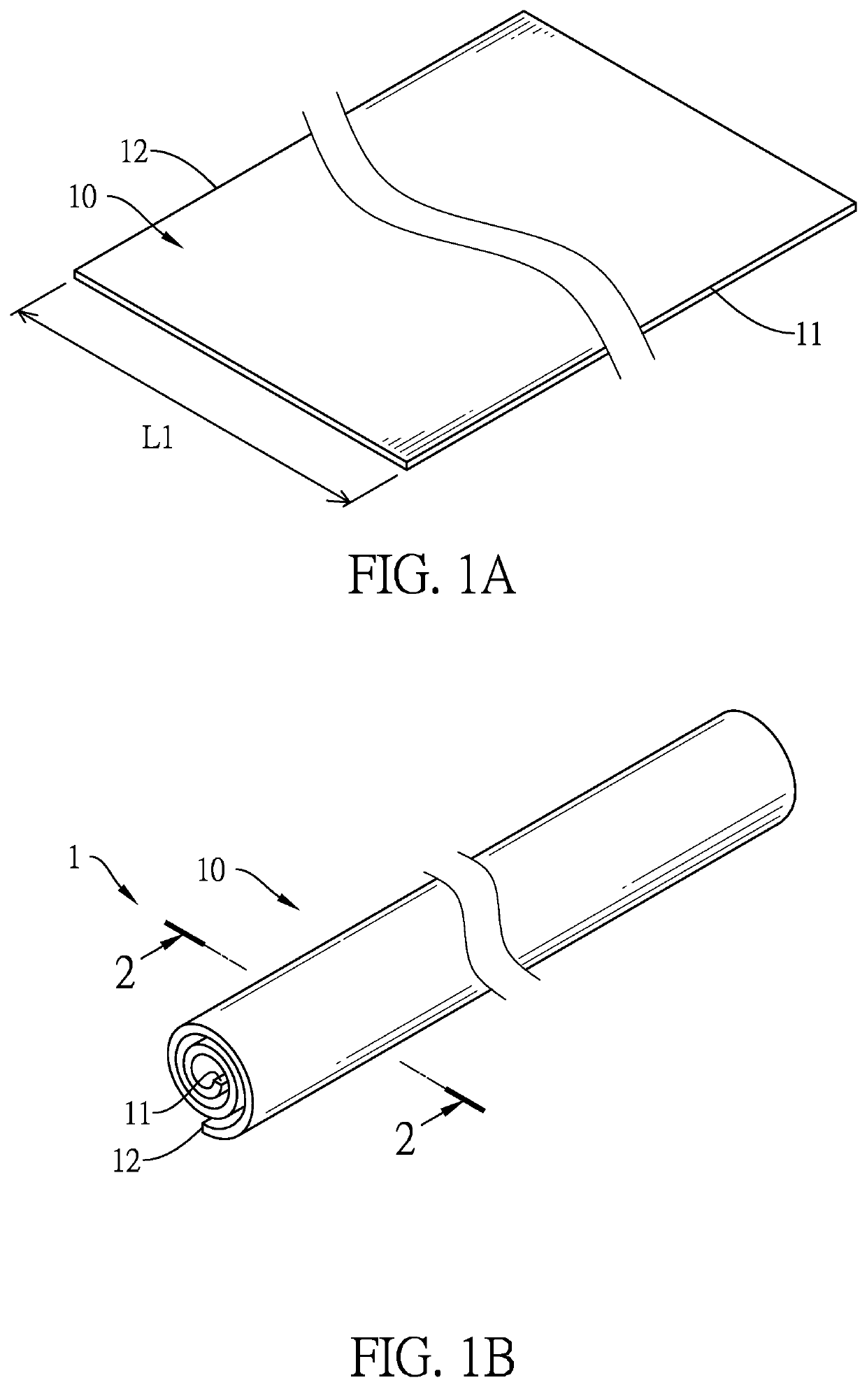
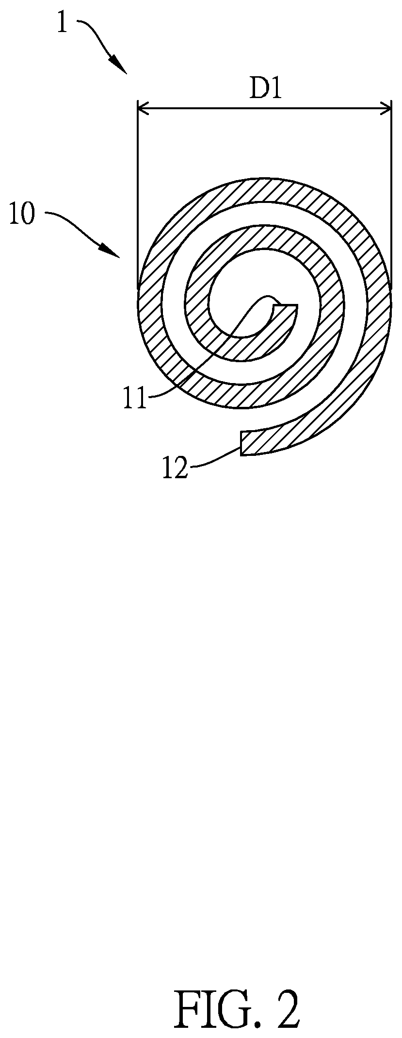
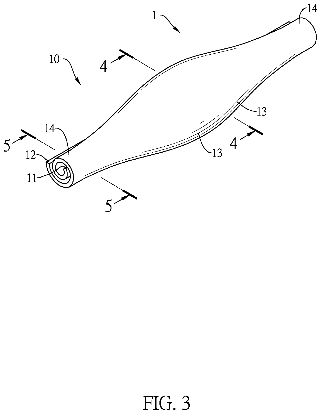
[0034]As shown in FIGS. 1A and 1B, the first preferred embodiment of the rolled retraction cord 1 has flexibility and plasticity. The rolled retraction cord 1 is made of a sheet 10 rolled into a non-firm multilayer strip. The sheet 10 having a smooth surface comprises a first side edge 11 and a second side edge 12, and the first side edge 11 and the second side edge 12 are opposite and parallel to each other. In particular, the rolled retraction cord 1 is formed by rolling the first side edge 11 of the sheet 1 toward the second side edge 12 of the sheet 10, wherein the thickness of the sheet 10 ranges from 0.05 mm to 0.15 mm, and the length L1 from the first side edge 11 to the second side edge 12 ranges from 2 mm to 15 mm. In this embodiment, the mate...


PUM

PropertyMeasurementUnit
length L1aaaaaaaaaa
length L1aaaaaaaaaa
outer diameter D1aaaaaaaaaa

Abstract

A method for manufacturing a rolled retraction cord is provided. The method comprises the steps of: (A) preparing the sheet, the sheet comprising a first side edge and a second side edge opposite to each other; (B) placing the sheet on a first surface of a first forming member; (C) contacting the first side edge of the sheet with a second surface of a second forming member, the first side edge of the sheet sandwiched between the first surface of the first forming member and the second surface of the second forming member; and (D) applying a force via the first surface or the second surface to the sheet, and rolling the sheet from the first side edge to the second side edge to obtain the retraction cord. With this method, a rolled retraction cord with a smooth surface and enhanced ductility is capable of being provided.

Description

BACKGROUND OF THE INVENTION1. Field of the Invention[0001]The present invention relates to a method for manufacturing the rolled retraction cord.2. Description of the Prior Arts[0002]In dental therapeutics, gingival retraction is a special method to temporarily distend and retract the gingiva away from teeth. For instances, when the tooth has caries near or below the gingival margin, gingival retraction is adopted to fill the gingival sulcus to separate the tooth and gingiva so the caries of the tooth can be exposed for the dentist to perform restoration; for prosthesis fabrication, the margin of the abutment tooth needs to be fully and accurately impressed. Since the dental crown or bridge margin design needs to be level with or below the gingival margin, gingival retraction is adopted to expose the margin of the abutment teeth to complete the impression of the teeth below the gingival margin. The most common process of gingival retraction is to place a retraction cord into the gin...

Claims


Application Information

Patent Timeline
Patent Type & Authority Applications(United States)
IPC IPC(8): A61C9/00B29C53/56B29C53/04B29C63/24
CPCA61C9/0033B29C53/566B29L2031/753B29C63/24B29C53/04B29C63/0069B29C63/26B29K2027/18B29K2105/256
Inventor KO, PING-LIANGLEE, TSE-ANGWU, JIN-GENFAN, KANG-HSIENWU, CHIEN-CHIANGLAI, HSIN-CHIHCHANG, FU-LONG
Owner CHANG FU LONG
Why Eureka
Try Eureka