Vehicle-body structure of vehicle

a vehicle and body technology, applied in the direction of vehicle components, vehicle arrangement, superstructure sub-units, etc., can solve the problems of inability to receive the tunnel reinforcement alone, occupant injuries, and prone to so as to reduce the deformation of the tunnel reinforcement as well as the floor tunnel, and reduce the deformation of the floor tunnel. , the effect of increasing the rigidity of the floor tunnel

Active Publication Date: 2021-03-11
MAZDA MOTOR CORP
View PDF0 Cites 13 Cited by
  • Summary
  • Abstract
  • Description
  • Claims
  • Application Information

AI Technical Summary

Benefits of technology

The present invention aims to prevent deformation of the floor tunnel in a vehicle caused by side collision loads from the cross member to the floor tunnel via the seat mounting bracket. The technical effect of this invention is to enhance the overall safety and stability of the vehicle body structure in the event of a side collision.

Problems solved by technology

In general, if a B pillar (center pillar) of a vehicle such as an automobile intrudes into a passenger compartment of the vehicle under a side collision load that acts on a side sill at a side of the vehicle due to another vehicle colliding with the side of the vehicle or the side of the vehicle colliding with an obstacle, an occupant will be injured.
However, the vehicle-body structure disclosed in Japanese Patent Laid-Open No. 2019-014354 has the following problem.
When the vehicle includes a floor tunnel with a huge cross-section like the aforementioned FR vehicle, the tunnel reinforcement itself becomes large, and thus the side collision load, which is transmitted from the cross member to the tunnel reinforcement via the seat mounting bracket and the floor tunnel, cannot be received by the tunnel reinforcement alone.
This renders the floor tunnel prone to deformation.

Method used


Image

  • Vehicle-body structure of vehicle
  • Vehicle-body structure of vehicle
  • Vehicle-body structure of vehicle

Examples


Embodiment Construction

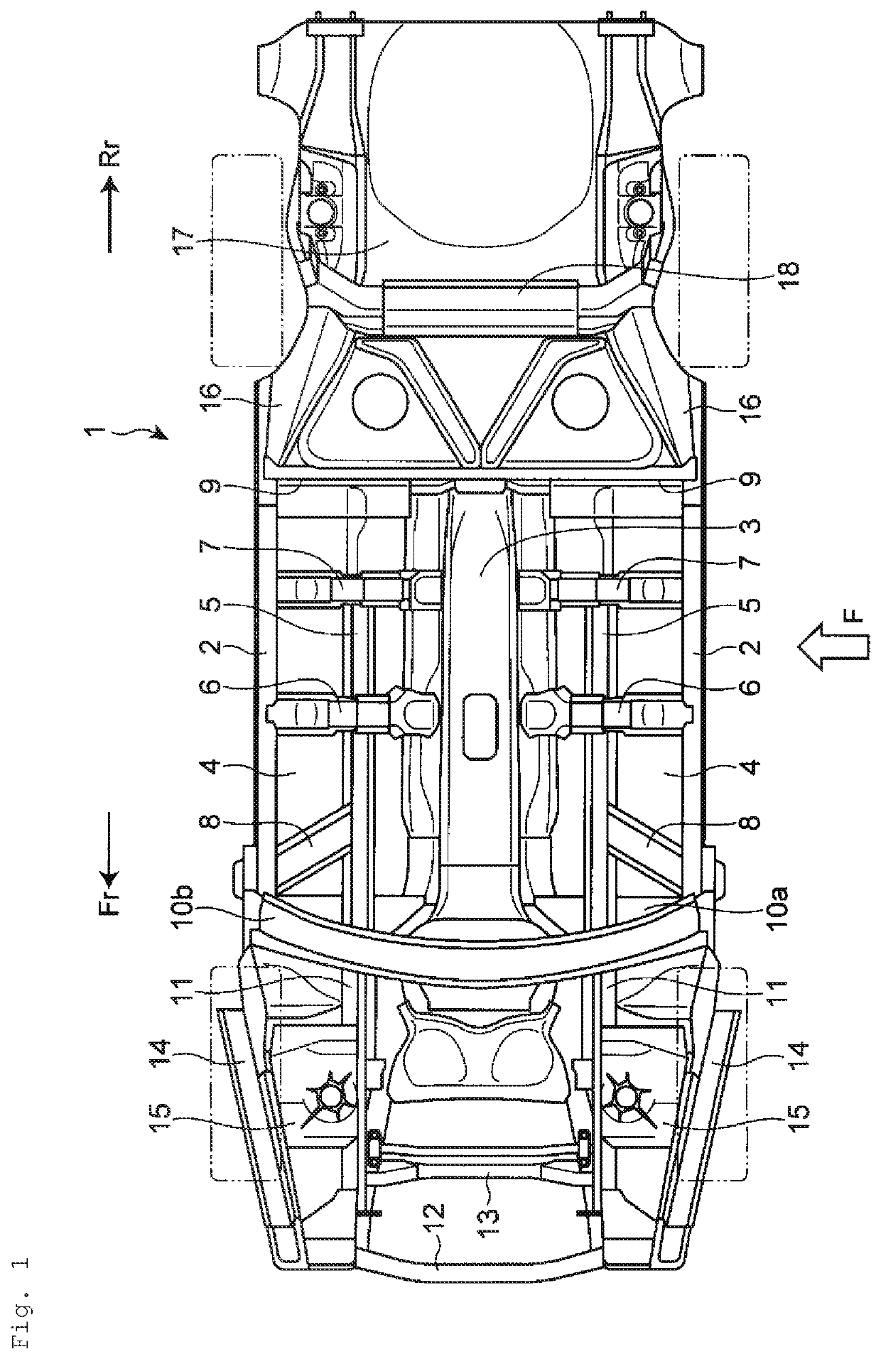
[0030]An embodiment of the present disclosure will be described below with reference to the accompanying drawings. Throughout the drawings, reference characters Fr and Rr respectively refer to a front side (or frontward) and a rear side (or rearward) of an automobile, and reference characters OUT and IN respectively refer to an outside (or outward) and an inside (or inward) of the automobile in the vehicle width direction.

[0031]FIG. 1 shows a lower vehicle-body 1 of the automobile having a vehicle-body structure of a vehicle according to an embodiment of the present disclosure. The lower vehicle-body 1 includes a pair of left and right side sills 2 extending in a vehicle front-rear direction, a floor tunnel 3 disposed at a center in the vehicle width direction between the pair of left and right side sills 2 and extending in the vehicle front-rear direction, and floor panels 4 extending from vehicle-width-direction inner side ends of the pair of left and right side sills 2 toward a v...


PUM


Abstract

A vehicle-body structure which prevent deformation of a floor tunnel caused by a side collision load transmitted from a cross member to the floor tunnel via a seat mounting bracket. A pair of left and right backbone frames extending in a vehicle front-rear direction are provided each of which faces a top and a side of a floor tunnel and is fixed to the floor tunnel. A tunnel reinforcement is provided that includes a front projection, an intermediate projection, and a rear projection abutting on an underside of the floor tunnel. The backbone frame includes multiple beads abutting on the floor tunnel. The tunnel reinforcement is fixed at the front projection, the intermediate projection, and the rear projection to the seat mounting bracket via the floor tunnel and is also fixed to the multiple beads of the backbone frame via the floor tunnel.

Description

BACKGROUNDTechnical Field[0001]The present disclosure relates to a vehicle-body structure of a vehicle that can withstand a collision from a side of the vehicle.Background Art[0002]In general, if a B pillar (center pillar) of a vehicle such as an automobile intrudes into a passenger compartment of the vehicle under a side collision load that acts on a side sill at a side of the vehicle due to another vehicle colliding with the side of the vehicle or the side of the vehicle colliding with an obstacle, an occupant will be injured. Thus, a cross member extending in a vehicle width direction of the vehicle has been used to receive the side collision load acting on the side sill and prevent the B pillar from intruding into the passenger compartment.[0003]In vehicles such as front-engine rear-drive (FR) vehicles and four-wheel drive (4WD) vehicles, a floor tunnel extending in a front-rear direction and having a huge cross-section is provided to dispose a propeller shaft that transmits pow...

Claims


Application Information

Patent Timeline
Patent Type & Authority Applications(United States)
IPC IPC(8): B62D25/20B62D25/02B62D21/02B60N2/015
CPCB62D25/2036B60N2/015B62D21/02B62D25/025B62D21/157B62D25/20
Inventor EBISUMOTO, KEISUKENATSUME, HIROTAKAKAGEYAMA, KAZUHIRO
Owner MAZDA MOTOR CORP
Why Eureka
Try Eureka