Holder facility for holding a medical instrument

Pending Publication Date: 2021-04-01
CORINDUS
View PDF0 Cites 2 Cited by
  • Summary
  • Abstract
  • Description
  • Claims
  • Application Information

AI Technical Summary

Benefits of technology

[0092]Through this, a flexible use of the coordination facility may be made possible.
[0093]Through the forms of embodiment of the coordination facility described above, s

Problems solved by technology

While the high mechanical flexibility and/or deformability of the medical instruments frequently represents an important basis for use in an intervention and/or examination, precise guidance of the instrument may be rendered more difficult by the attributes.
In this facility (e.g., through friction between the guidance facility and the catheter), this

Method used


Image

  • Holder facility for holding a medical instrument
  • Holder facility for holding a medical instrument
  • Holder facility for holding a medical instrument

Examples


Embodiment Construction

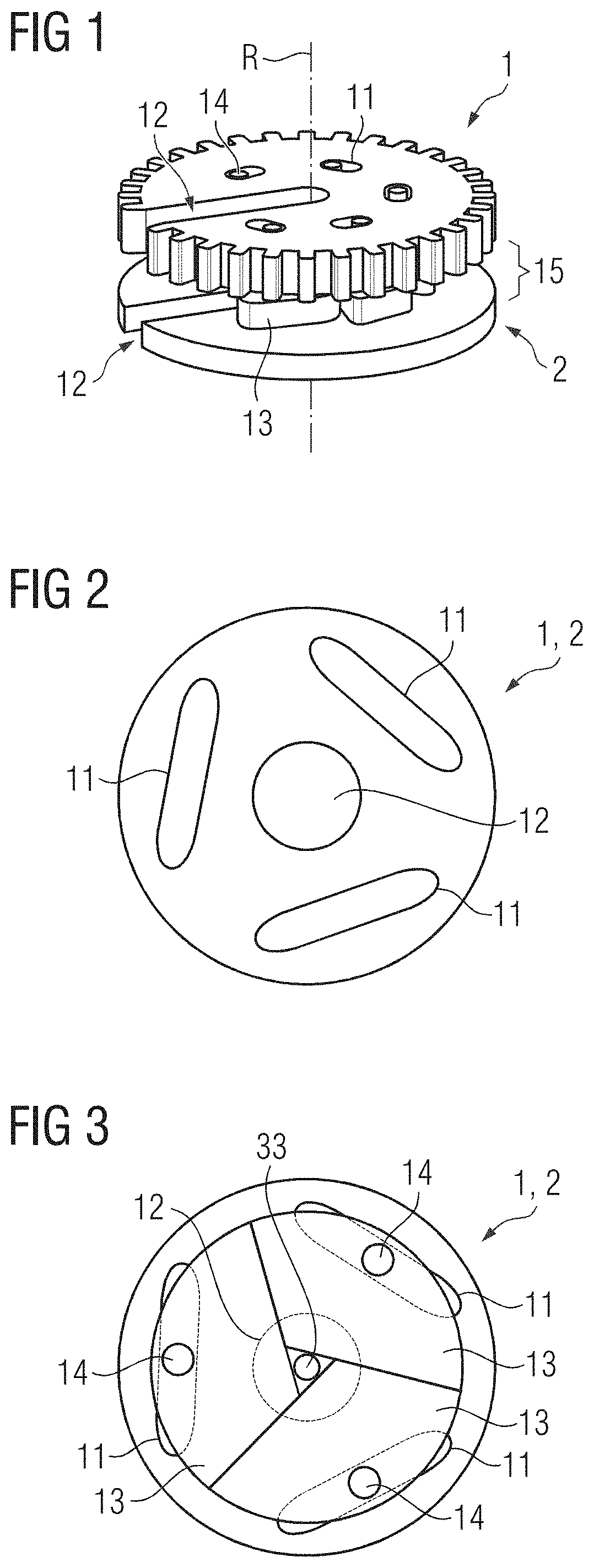
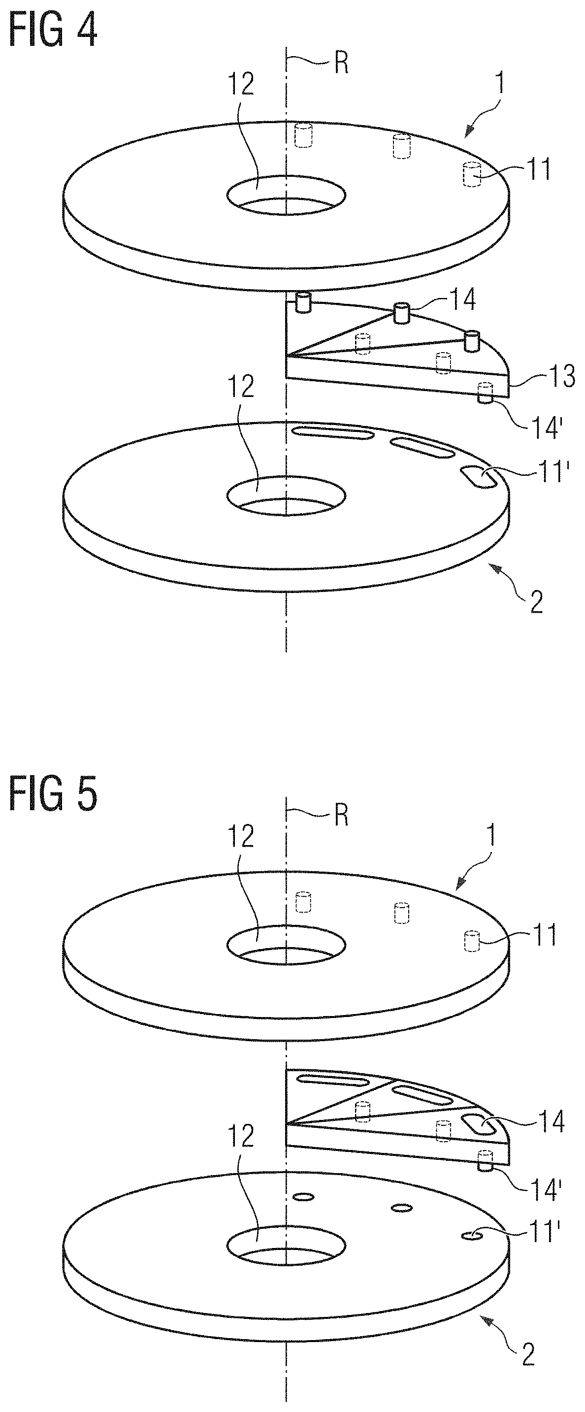
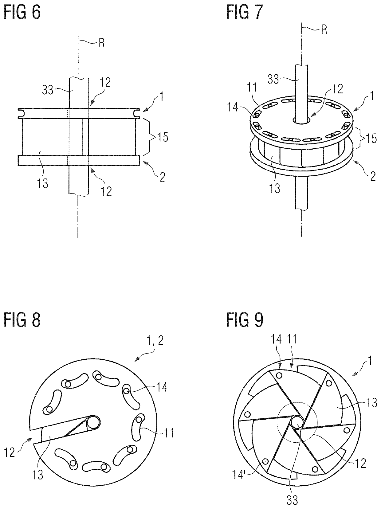
[0151]FIG. 1 schematically shows one embodiment of a holder facility (e.g., a holder). In this figure, the holder facility may include a first receiving element 1, a second receiving element 2, and at least three diaphragm elements 13. The at least three diaphragm elements 13 may further be arranged within a diaphragm layer 15 between the first receiving element 1 and the second receiving element 2 about a common axis of rotation R. In this figure, the common axis of rotation R may run essentially at right angles (e.g., not in parallel) to the diaphragm layer 15. In this figure, the first receiving element 1 and the second receiving element 2 may each have an opening 12 for receiving the medical instrument (not shown here). The first receiving element 1 and the second receiving element 2 may further be able to be moved about the common axis of rotation R relative to one another. The at least three diaphragm elements 13 may each have at least one first coupling element 14. The first ...


PUM


Abstract

A holder facility for holding a medical instrument includes a first receiving element, a second receiving element, and at least three diaphragm elements. The at least three diaphragm elements within a diaphragm layer are arranged between the first and second receiving elements about a common rotation axis. The first and second receiving elements each have an opening for receiving the medical instrument. The first and second receiving elements are movable around about the common rotation axis relative to one another. Each of the at least three diaphragm elements is forcibly moved by mechanical coupling. For a movement of the first receiving element relative to the second receiving element about the common rotation axis, there is a forcibly-guided movement of the at least three diaphragm elements such that the at least three diaphragm elements hold a medical instrument arranged in the opening of the first and second receiving elements.

Description

[0001]This application claims the benefit of German Patent Application No. DE 10 2019 214 868.9, filed on Sep. 27, 2019, which is hereby incorporated by reference in its entirety.BACKGROUND[0002]The present embodiments relate to a holder facility for holding a medical instrument.[0003]For the precise examination of an object to be examined (e.g., for vascular diseases and / or tumor diseases, as well as for interventions, such as for vasodilation and / or for placement of an angioplasty in the object being examined), elongated and / or flexible medical instruments are frequently used. In such cases, the object being examined may be a human and / or animal patient, for example. The medical instrument is further frequently embodied as a surgical instrument (e.g., as a catheter and / or guide wire, and / or as a diagnostic instrument, such as an endoscope with an ultrasound head for a transesophageal echocardiogram (TEE probe), and / or a bronchoscope). While the high mechanical flexibility and / or d...

Claims


Application Information

Patent Timeline
IPC IPC(8): A61B90/57A61B1/00A61B34/30
CPCA61B90/57A61B2034/301A61B34/30A61B1/00149A61B90/50A61B8/12A61B8/42A61B1/00147A61M25/02A61B90/98A61B90/39A61B2090/5025
Inventor FINOCCHI, RODOLFOKAPOOR, ANKURGIRARD, ERINKIM, YOUNG-HOMANSI, TOMMASO
Owner CORINDUS
Why Eureka
Try Eureka