Folding System

a folding system and system technology, applied in the field of folding systems, can solve problems such as relative complexity, and achieve the effects of reducing the risk of guide rail or pin bending, high wind load, and reliable closing action of folding systems

Pending Publication Date: 2021-04-01
SOLARLUX ALUMINUM SYST
View PDF0 Cites 1 Cited by
  • Summary
  • Abstract
  • Description
  • Claims
  • Application Information

AI Technical Summary

Benefits of technology

[0006]By providing at least one locking pin functioning as a reinforcement pin in the frame section of the same folding wing in which also the locking pin is located, the two pins can be connected parallel but fixedly to each other with regard to their movement so that the reinforcement pin is arranged to be moved together with the locking pin. A coupling extending through the movable intermediate space between two folding wings is therefore not required. The locking action of both pins can still be realized by means of only one locking gear. Due to the additional reinforcement pin, the locking forces act however at several locations (locking pin and reinforcement pin); the load or force on the individual pins is thus at least cut in half. In case of burglary attempts or in case of wind loads acting on the folding system, the force introduction into the guide rail is distributed in an improved way and reduces the risk of bending of the guide rail or of the pins. When neighboring folding wings are connected by hinges, the improved locking action extends also to the folding wing that is neighboring the locking action. The locking action according to the invention can however be used also in relation to a wall or used in case of folding wings which are not fixedly connected to a neighboring wing, in particular not connected by hinges.
[0007]In addition to securing against burglary, a reliable closing action of folding systems at high wind loads is advantageous in particular. In this context, it is particularly positive when the reinforcement pin is accommodated in a supplemental reinforcement section of the frame section so that the stability of the folding wing against bending is increased. With an appropriate configuration, bending of the folding wing at wind load can be reduced so much that there is no risk anymore that locking pin and reinforcement pin can jump out of the guide rails. Also, a supplemental reinforcement section, in particular when it is detachably connected to the existing frame section piece, can be retrofitted without problem or can be provided only when needed. However, it is also possible to configure the reinforcement section as one piece together with the section piece that accommodates the locking pin.
[0008]An improvement of the stability can also be achieved when the frame section comprises a blade-shaped projection that extends vertically and counteracts bending. The projection has preferably a strip-shaped or blade-shaped configuration with a height that preferably occupies most of the height of the vertical frame section. Compared thereto, the width of the projection is rather minimal, and its depth, i.e., its extension measured perpendicular to the plane of the folding wing, is preferably larger than its width. The projection can be embodied as one piece together with the frame section or can be connected to it. When this projection is arranged at the reinforcement section, the number of required components for various embodiments can however be kept small because the required stability can be adjusted, as needed, by selecting a suitable reinforcement section, with or without projection.
[0009]In a constructively simple way, without having to modify the configuration of the locking gear, the reinforcement pin can be connected by means of an adapter piece to the locking pin. In case of retrofitting, it can be advantageous when the adapter piece for this purpose has a mounting cutout which enables access by a tool for producing the connection. The adapter piece can be designed substantially in a C shape or U shape for this purpose.

Problems solved by technology

This construction provides for an increased protection against burglary but is relatively complex.

Method used


Image

  • Folding System
  • Folding System
  • Folding System

Examples


Embodiment Construction

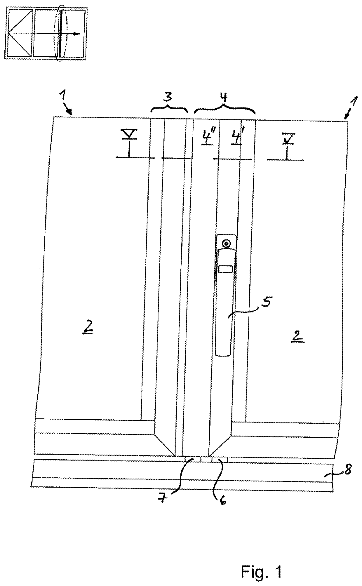
[0021]FIG. 1 shows the bottom region of two folding wings 1 connected to each other in the closed functional position of the locking action. At the top to the left there is a small pictograph illustration of an exemplary folding system for illustrating the function. The illustrated folding wings 1 are guided in a guide comprising a top guide rail and a bottom guide rail 8. The illustrated folding wings 1 each have glass panes 2 which are secured in frame sections 3, 4. The folding wing 1 to the right in the illustration comprises a locking action that can be actuated by means of a grip 5. By means of the grip 5, a locking pin 6 and a reinforcement pin 7 can be moved into the bottom guide rail 8 so that pivoting of the folding wings can be prevented. The locking pin 6 is guided in a section piece 4′ of the frame section 4 while the reinforcement pin 7 is accommodated in a reinforcement section 4″ of the frame section 4.

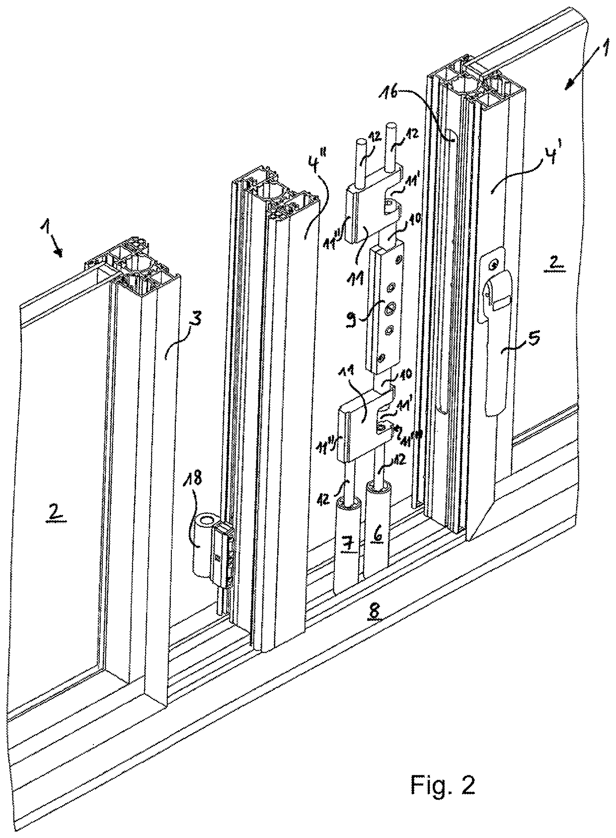
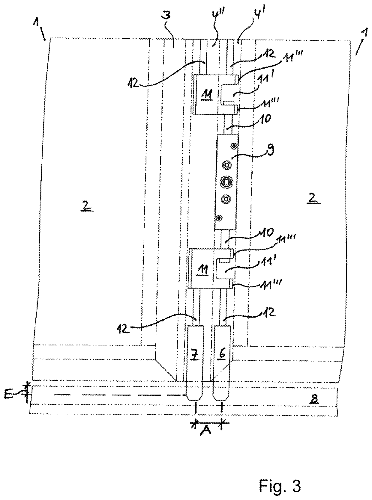
[0022]FIGS. 2 through 5 illustrate the function and the individua...


PUM


Abstract

A folding system has a bottom guide rail and a top guide rail. A first folding wing and a second folding wing are supported movably in the bottom guide rail and the top guide rail, respectively. The first folding wing has a vertically extending frame section. A lock fitting is arranged in the vertically extending frame section of the first folding wing and has a vertically slidably supported locking pin. A locking gear is connected to the locking pin and can move the locking pin into and out of one of the bottom and top guide rails. A reinforcement pin is arranged parallel to the locking pin in the vertically extending frame section of the first folding wing. The locking pin and the reinforcement pin are connected to each other such that the reinforcement pin is entrained parallel to the locking pin when the locking gear is actuated.

Description

BACKGROUND OF THE INVENTION[0001]The invention relates to a folding system, especially a glazed folding system, with at least two folding wings that are movably guided in a guide comprising guide rails at the top and at the bottom. At least one folding wing comprises a frame section that extends vertically and accommodates a lock fitting with at least one locking pin that is supported so as to be vertically slidable and is arranged to be moved into and out of the guide rail at the top and / or at the bottom by means of a locking gear.[0002]For opening the folding wings of the folding system, the folding wings can be moved in the guide rails and / or can be pivoted out of the guide rails. In the closed position, a locking action is required. For this purpose, a lock fitting is accommodated in the frame section of at least one of the folding wings. By means of a locking gear, locking pins can be moved at least at the top and at the bottom into the guide rail or moved out of the guide rail...

Claims


Application Information

Patent Timeline
Patent Type & Authority Applications(United States)
IPC IPC(8): E05C9/04E06B3/92E06B3/48E05C9/22
CPCE05C9/04E05C9/22E06B3/481E06B3/924E05B65/0085E05B15/108E05C9/185
Inventor NUSSBAUM, BJÖRN
Owner SOLARLUX ALUMINUM SYST
Why Eureka
Try Eureka