
Digital water timer

a digital and timer technology, applied in the field of water timers, can solve the problems of limited visual angles and inconvenient use of water timers, and achieve the effect of easy dust removal of display panels and optimal view for operation

Active Publication Date: 2021-04-15
SHIN TAI SPURT WATER OF THE GARDEN TOOLS
View PDF0 Cites 2 Cited by
  • Summary
  • Abstract
  • Description
  • Claims
  • Application Information

AI Technical Summary

Benefits of technology

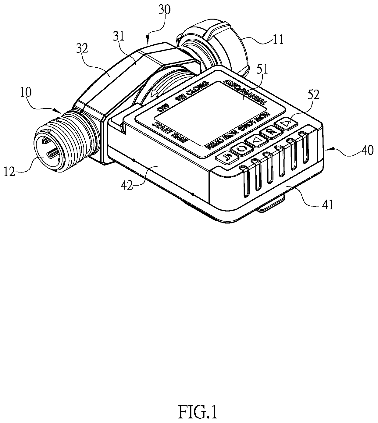
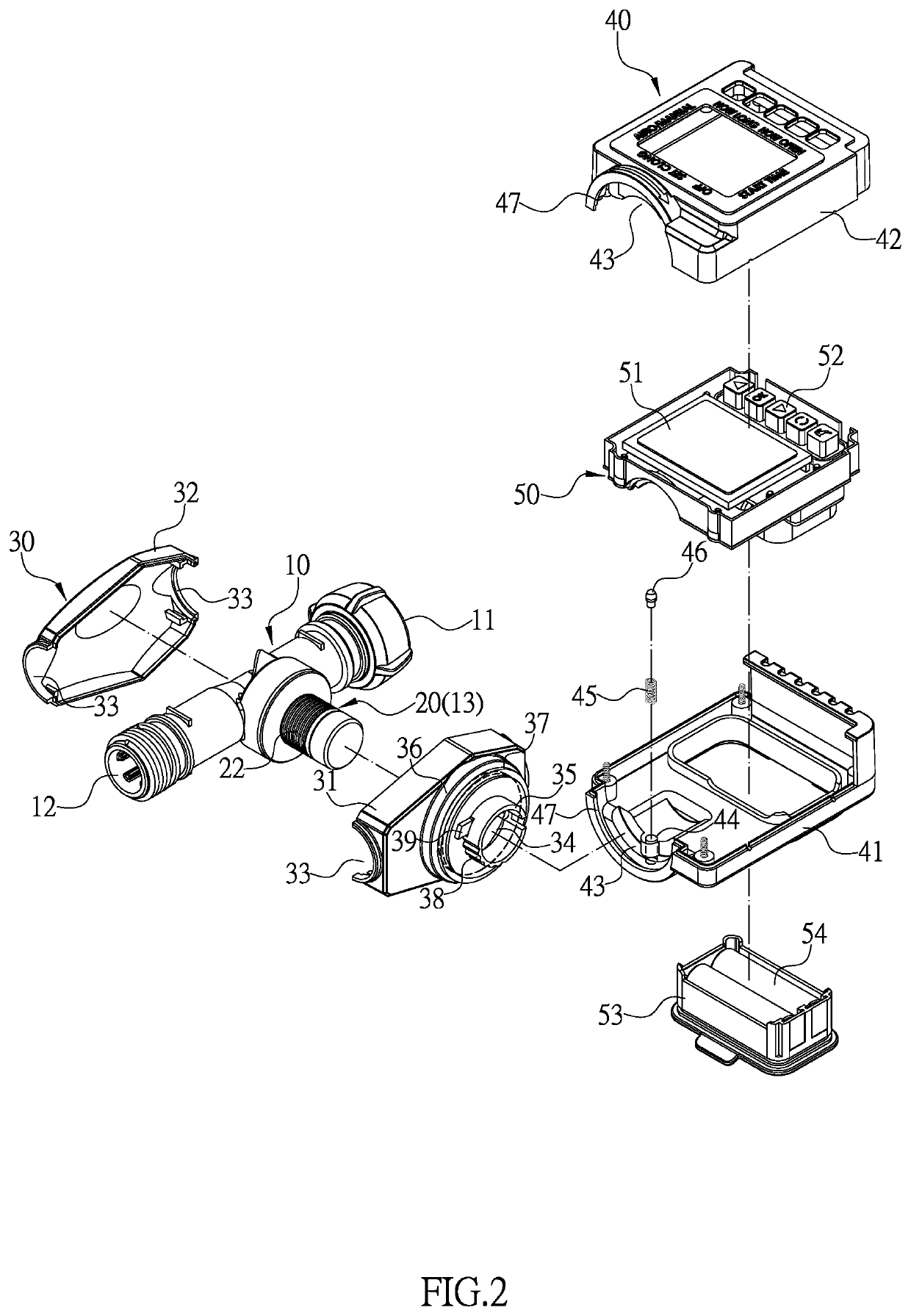
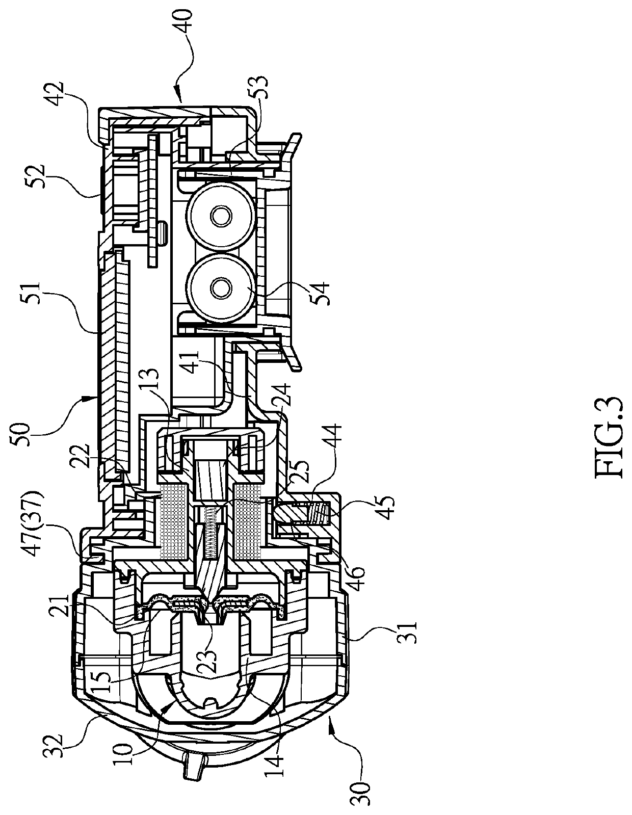
[0005]Comparing with conventional water timer, the present invention is advantageous because: (i) the driving base together with the timer and the display panel can be pivotally rotated relative to the locating base and secured at a position having an optimal view for operation, which enables the display panel to be used as needed under different conditions; (ii) the timer can be rotated to a vertical angle to enable a user to pat the dust off the display panel easily; and (iii) the driving base with the display panel can be adjusted to a position having an optimal view for operation both when the main body is positioned vertically and when the main body is positioned horizontally.

Problems solved by technology

However, the conventional digital water timer has following disadvantages: the timer (70) with the display panel (73) is secured on the water valve (60) and cannot be rotated relative to the water valve (60), and the display panel (73), which usually is a LCD, has its limited in visual angles, so that the water timer is inconvenient to use when the display panel (73) is unable to rotate and adjust as needed and is easily restricted by factors such as light direction and terrain.

Method used


Image

  • Digital water timer
  • Digital water timer
  • Digital water timer

Examples


Embodiment Construction

[0017]The detailed description set forth below is intended as a description of the presently exemplary device provided in accordance with aspects of the present invention and is not intended to represent the only forms in which the present invention may be prepared or utilized. It is to be understood, rather, that the same or equivalent functions and components may be accomplished by different embodiments that are also intended to be encompassed within the spirit and scope of the invention.

[0018]Unless defined otherwise, all technical and scientific terms used herein have the same meaning as commonly understood to one of ordinary skill in the art to which this invention belongs. Although any methods, devices and materials similar or equivalent to those described can be used in the practice or testing of the invention, the exemplary methods, devices and materials are now described.

[0019]All publications mentioned are incorporated by reference for the purpose of describing and disclos...


PUM


Abstract

A digital water timer may include a main body, a water valve, a locating base, a driving base, and a timer. The main body has a water inlet and a water outlet, and a valve tube protrudes from a lateral side of the main body. The water valve connected to the main body is controlled by the timer to achieve on / off operation of channels inside the main body. The locating base is secured on the main body, and the driving base is adapted to have rotation relative to the locating base and be secured at a specific position after rotated. The timer installed in the driving base comprises a display panel and an operation interface which are exposed externally for operation. The driving base with the timer is rotated relative to the locating base, and the display panel is adjusted as needed to provide an optimal view for operation.

Description

FIELD OF THE INVENTION[0001]The present invention relates to a water timer and more particularly to a digital water timer that enables its display panel to be adjusted in angles.BACKGROUND OF THE INVENTION[0002]Referring to FIGS. 10 and 11, a conventional water timer comprises a water valve (60) and a timer (70). The water valve (60) has a water inlet (61) and a water outlet (62), and an electromagnetic solenoid (63) is formed at a lateral side of the water valve (60). The electromagnetic solenoid (63) is electrically connected to the timer (70) so as to control on / off operation of the water valve (60). The timer (70) is installed on the water valve (60) to provide power supply to the electromagnetic solenoid (63). Moreover, the timer (70) comprises a main body (71) which firmly covers and is connected to the electromagnetic solenoid (63), and the main body (71) has a solar panel (72), a display panel (73), and an operation interface (74) thereon. When in use, the water valve (60) i...

Claims


Application Information

Patent Timeline
Patent Type & Authority Applications(United States)
IPC IPC(8): A01G25/16E03B7/04E03B7/07F16K31/48E03C1/04G09G3/3233
CPCA01G25/165E03B7/04E03B7/071G09G3/3233A01G25/162E03C1/04F16K31/48B05B1/3013B05B12/02F16K27/0281F16K31/082F16K31/404B05B12/082E03C1/055E03C1/057F16K31/084Y10T137/8158Y10T137/86389
Inventor CHEN, CHIN-YUAN
Owner SHIN TAI SPURT WATER OF THE GARDEN TOOLS
Learn More