
Passenger compartment structure

Pending Publication Date: 2021-04-15
MAZDA MOTOR
View PDF0 Cites 0 Cited by
  • Summary
  • Abstract
  • Description
  • Claims
  • Application Information

AI Technical Summary

Benefits of technology

The present invention provides a passenger compartment structure that allows for power saving while ensuring thermal comfort for the occupant. The structure includes a layered interior member that can control the temperature of the occupant's lower legs. The surface layer is made up of a layer of foam, while the underlying structural parent layer is made up of a composite material. The temperature control mechanism layer is made up of a layer of foam with a special design to regulate heating and cooling. This layered structure helps to provide a comfortable environment for the passenger while saving energy.

Problems solved by technology

Since the space occupied by the occupant is narrow and the posture is restricted, and heat insulation from the external environment is low in an environment inside the passenger compartment, in order to secure thermal comfort of the occupant, a lot of energy consumption is required.
Since transmission heating needs an amount of heat transmitted to a wall surface inside the passenger compartment (wall surface heat transmission amount) and the ventilation load for raising the temperature of the ventilation air, there is a risk that the air conditioning power consumption may increase.
However, the technology of Patent Literature 1 is still transmission heating, and there is room for improvement from the viewpoint of power saving because power consumption occurs due to the wall surface heat transmission amount and ventilation load.
In particular, in electric vehicles and hybrid vehicles, which have been increasing in recent years, there is a risk that an increase in power consumption for air conditioning may cause a decrease in a cruising range because waste heat from an engine, which is a heat source, cannot be expected.
However, if a large amount of temperature control units such as heater panels are disposed on the wall surface inside the passenger compartment, there is a concern that production costs will increase as the number of parts of the vehicle increases.
In addition, there is also a risk that power consumption for operating the large number of heater panels increases and expected power saving cannot be secured.

Method used


Image

  • Passenger compartment structure
  • Passenger compartment structure
  • Passenger compartment structure

Examples


Embodiment Construction

[0037]An embodiment of the present invention will be described in detail below with reference to the drawings.

[0038]The following description exemplifies the present invention applied to a passenger compartment structure of a vehicle including an indoor temperature control device, and does not limit the present invention, applications thereof, or uses thereof.

[0039]In the drawings, descriptions are given assuming that an arrow F direction is a frontward direction of the vehicle, an arrow L direction is a leftward direction, and an arrow U direction is an upward direction.

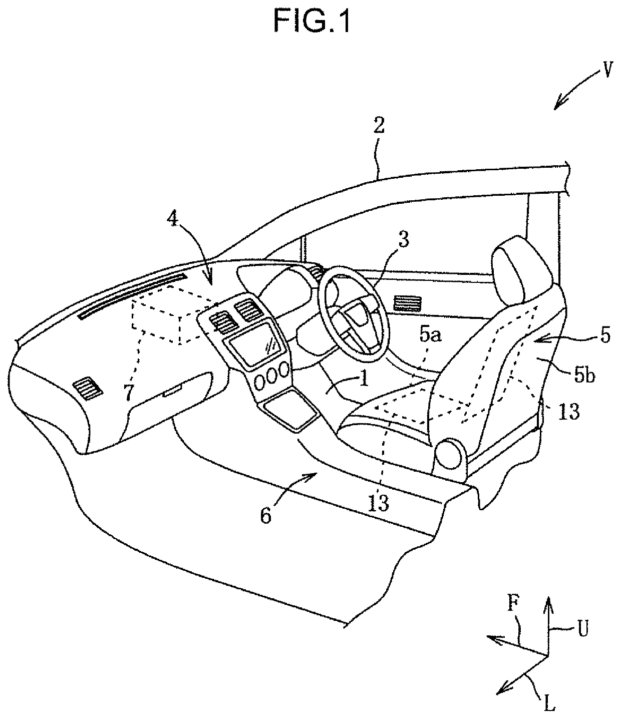
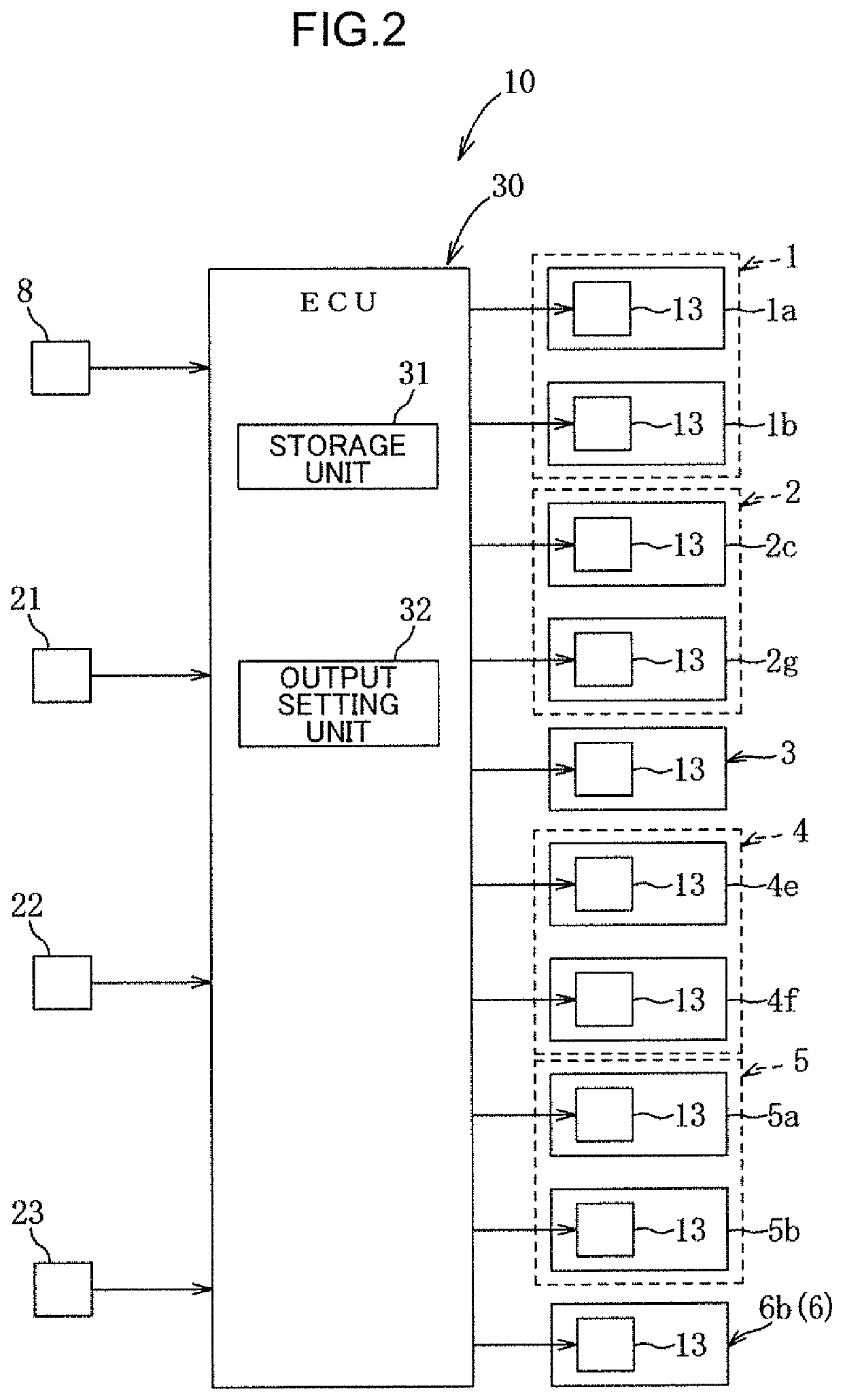
[0040]The embodiment of the present invention will be described below with reference to FIGS. 1 to 20. Note that FIG. 1 is an enlarged view of a portion around a driver's seat in a front right half of the passenger compartment in order to show main parts of the passenger compartment structure.

[0041]As shown in FIGS. 1 and 2, a vehicle V according to the present embodiment includes: a floor panel 1 constituting a pas...


PUM


Abstract

There is provided a passenger compartment structure that can save power while ensuring thermal comfort of an occupant. The passenger compartment structure allows control of thermal comfort of the occupant in a posture seated on a seat. The passenger compartment structure includes a layered structure constituting at least part of an interior member disposed at a position where the interior member is able to face a lower leg of the occupant. The layered structure disposed in each of a front middle portion, a front lower portion, a frontal lower portion, and a right surface front upper portion having a high geometric factor for the lower leg includes a surface layer, a structural parent layer, and a temperature control mechanism layer interposed between the surface layer and the structural parent layer.

Description

TECHNICAL FIELD[0001]The present invention relates to a passenger compartment structure, and particularly to a passenger compartment structure that enables control of thermal comfort of an occupant in a seated posture.BACKGROUND ART[0002]Conventionally, from the viewpoint of keeping one's head cool and one's feet warm, a vehicle air conditioning device is provided with a foot air outlet that can supply warm air to the feet of an occupant to raise the ambient temperature around legs of the occupant.[0003]Since the space occupied by the occupant is narrow and the posture is restricted, and heat insulation from the external environment is low in an environment inside the passenger compartment, in order to secure thermal comfort of the occupant, a lot of energy consumption is required.[0004]Here, the thermal comfort is defined in the American Society of Heating, Refrigerating and Air-Conditioning Engineers (ASHRAE) as “that state of mind which express satisfaction with the thermal envir...

Claims


Application Information

Patent Timeline
IPC IPC(8): B60H1/22B60R13/02
CPCB60H1/2226B60R2013/0287B60R13/0262A47C7/74B60H1/00B60H1/22B60R13/02B60H1/00285B60H1/00292B60H1/00295B60H2001/00307B60H1/00478B60H1/2227B60N2/5678
Inventor YOKOTA, KAZUYAOCHIAI, HIROYAOHSUMI, TOSHIHIKOKANEISHI, JUNJIYOSHIZUE, TOMOHIROKASHIMA, TOSHIHIRO
Owner MAZDA MOTOR
Features
  • Generate Ideas
  • Intellectual Property
  • Life Sciences
  • Materials
  • Tech Scout
  • Unparalleled Data Quality
  • Higher Quality Content
  • 60% Fewer Hallucinations
Learn More