
Charging holder for electronic devices

Active Publication Date: 2021-04-22
ICOM INC
View PDF0 Cites 2 Cited by
  • Summary
  • Abstract
  • Description
  • Claims
  • Application Information

AI Technical Summary

Benefits of technology

The present invention provides a charging holder for electronic devices that can be used in a car. The holder can accommodate different types of electronic devices without getting damaged during transportation. The lock mechanism is strong and secure, and the electronic devices can be easily detached from the holder. The holder is designed to prevent the lead wire from detaching from the connector terminal and reduces the number of parts needed for assembly. The holder is easy to use, even when driving, and allows for easy detachment of electronic devices.

Problems solved by technology

For this reason, although it can be used for desktop use, when it is used for in-vehicle vibration, the electronic device is easily detached from the charging holder and is not suitable for in-vehicle use.
It is also not suitable for wall hanging.

Method used


Image

  • Charging holder for electronic devices
  • Charging holder for electronic devices
  • Charging holder for electronic devices

Examples


Embodiment Construction

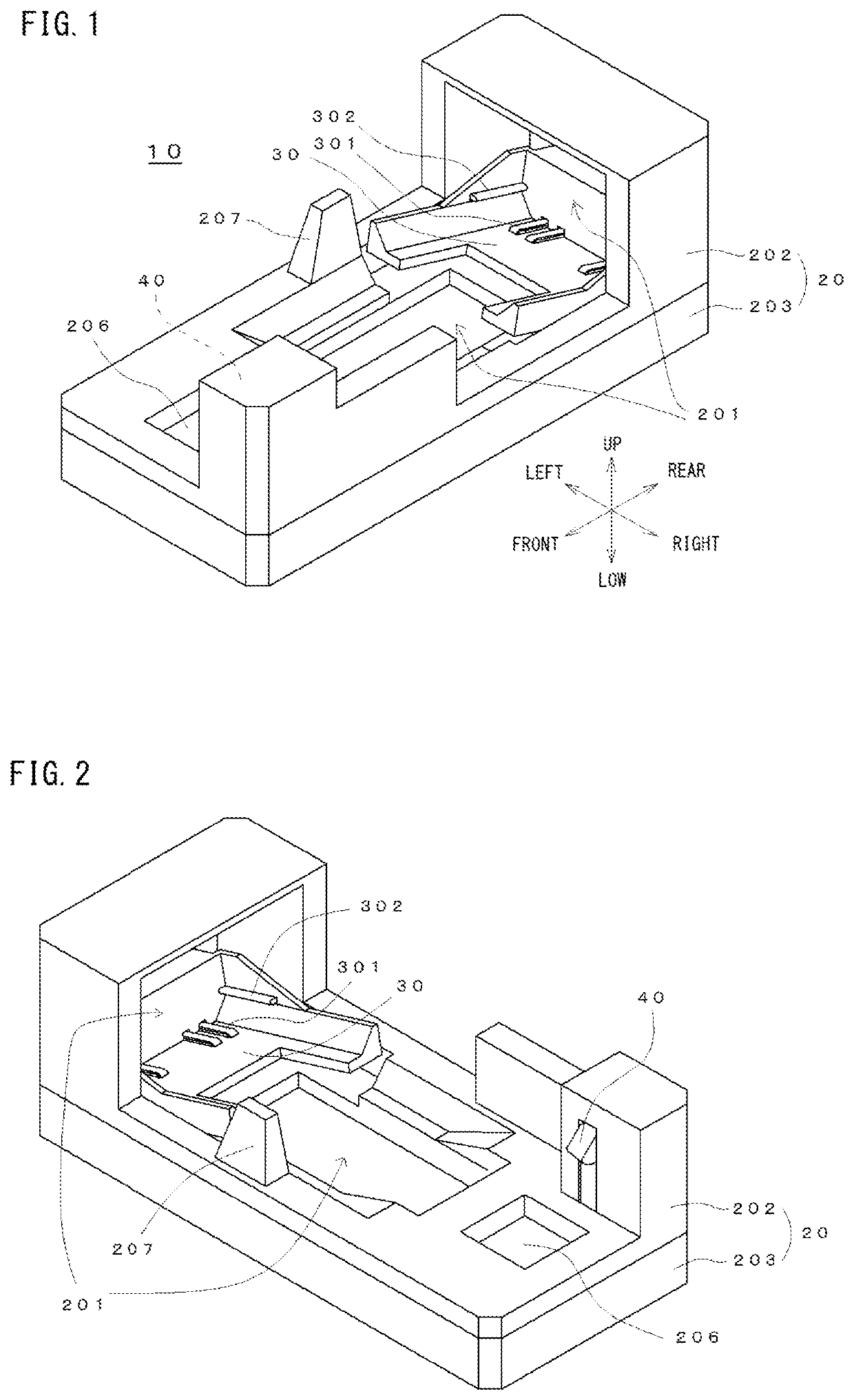
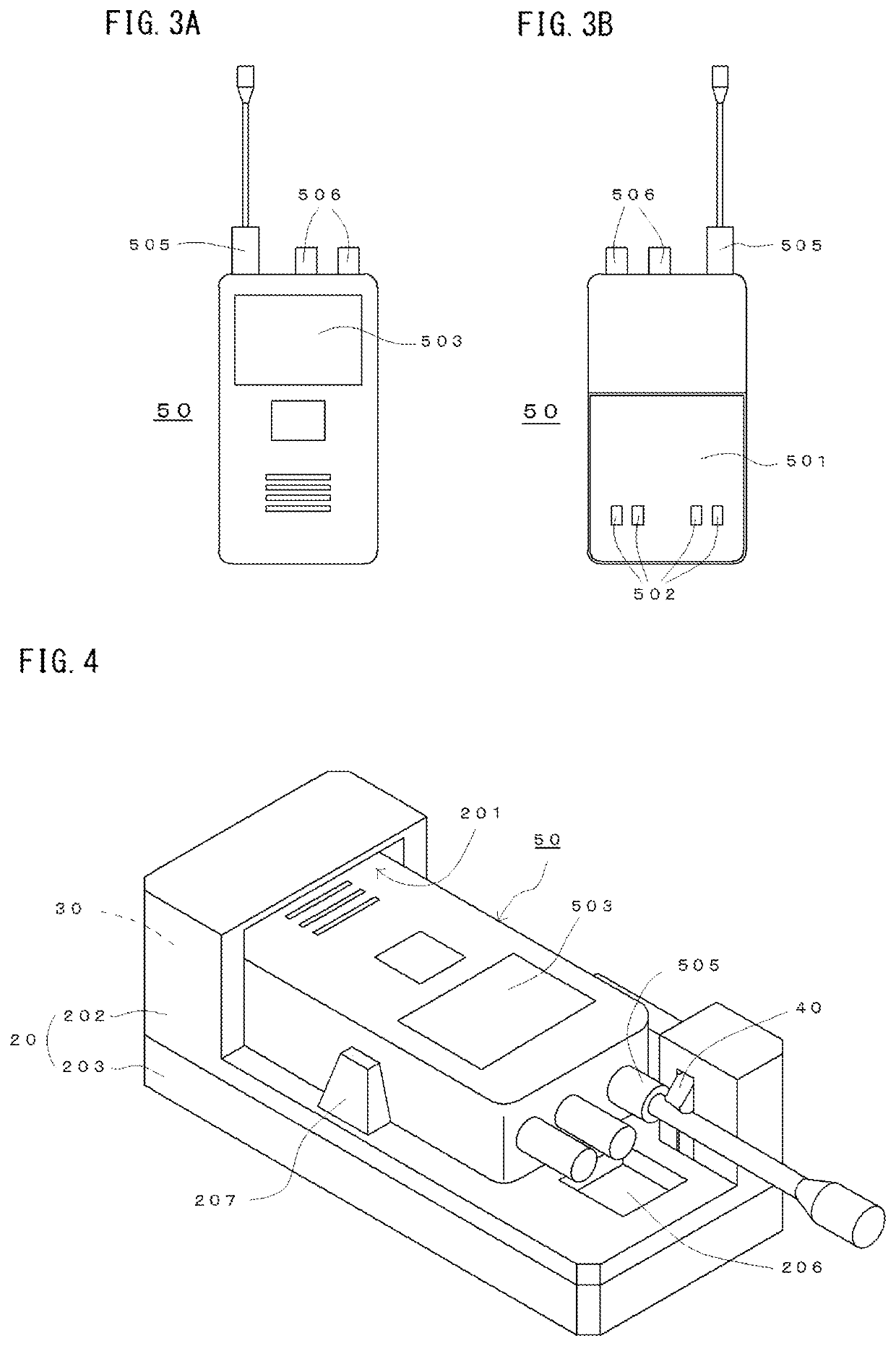
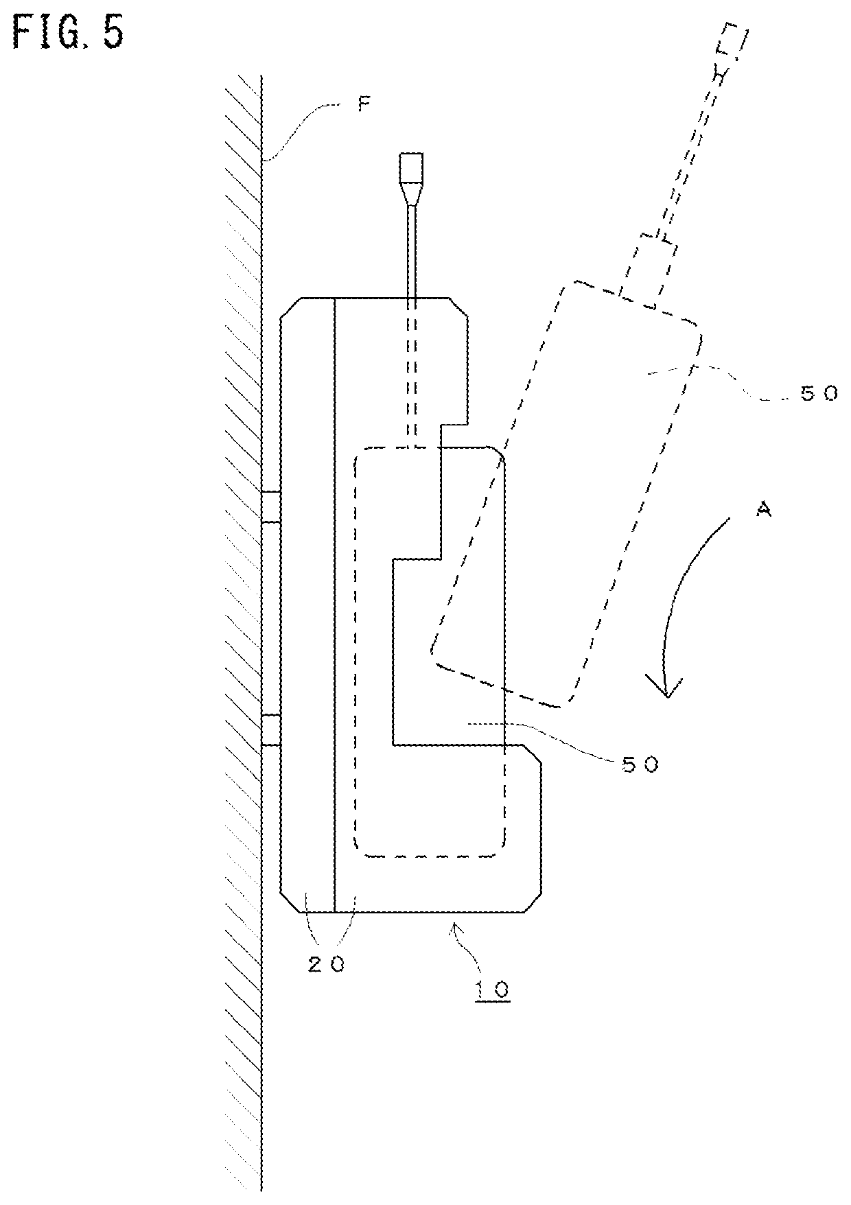
[0040]A charging holder for electronic devices (hereinafter referred to as a charging holder) according to an embodiment of the present invention will be described with reference to the drawings. The charging holder of this embodiment is for charging a battery by setting various devices such as a wireless device, a mobile phone etc. to which the battery or battery pack is mounted. In the present embodiment, an example which a wireless device is used as the electronic device will be described. As shown in the perspective view of FIG. 1, the diagonally lower left is referred to as the front, the diagonally upper right as the rear, the diagonally lower right as the right, and the diagonally upper left as the left.

(Structure of Charging Holder)

[0041]FIGS. 1 and 2 show a charging holder 10 according to the present embodiment.

[0042]The charging holder 10 includes a holder body 20 having a pocket 201 formed on the upper surface for inserting an electronic device. The holder body 20 include...


PUM


Abstract

A charging holder for electronic devices is shared for a plurality of electronic devices having different thickness, and is stably fixed even under vibration conditions. The holder has a holder body, a rotation block and a lock unit. A pocket for inserting an electronic device is formed in the holder body. The rotation block is rotated and biased so that a tip portion can protrude inside the pocket, and has a contact terminal which can contact a charging terminal of the electronic device. The lock unit is for locking the upper side of the electronic device to the holder body when the electronic device is pushed into the pocket and rotated. The rotation block is configured so that the lower part of the electronic device can be inserted therein, holds the lower part of the electronic device regardless of the thickness of the electronic device.

Description

[0001]This application claims the benefit of priority to Japanese Patent Application No. 2019-190752 filed on Oct. 18, 2019, the content of which is incorporated herein by reference.BACKGROUND OF THE INVENTION[0002]The present invention relates to a charging holder for electronic devices.[0003]As a charging holder for electronic devices having different dimensions, a plurality of holder has been proposed in which the same charging holder can be shared without preparing accessory parts (see, for example, Japanese Patent No. 5197470).[0004]In this charging holder, when the electronic devices are inserted into a pocket formed on an upper side of the holder body, a positioning member protruding inside the pocket applies a pressing force to the electronic device in a plurality of directions, then a charging terminal of the electronic device comes into contact with a contact terminal installed so as to protrude inside the pocket. According to this structure, the electronic device of vario...

Claims


Application Information

Patent Timeline
IPC IPC(8): H02J7/00B60R11/02
CPCH02J7/0044B60R11/0241H02J7/0045B60R2011/0075B60R2011/0085Y02E60/10
Inventor KAWAKI, KENNISHIZAWA, HARUKI
Owner ICOM INC
Learn More