
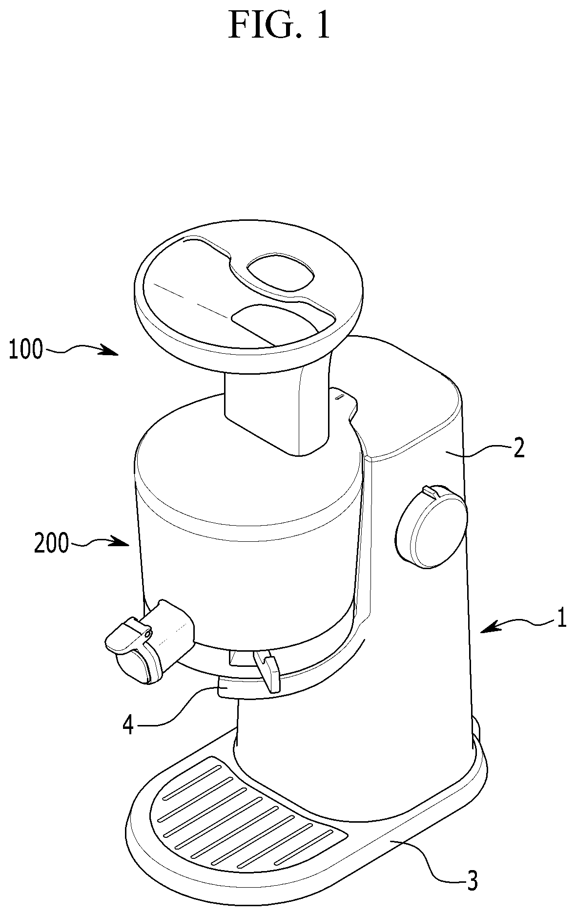
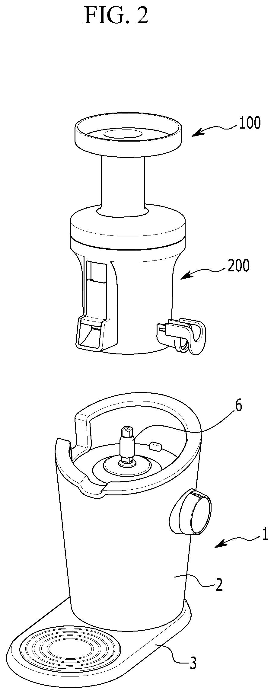
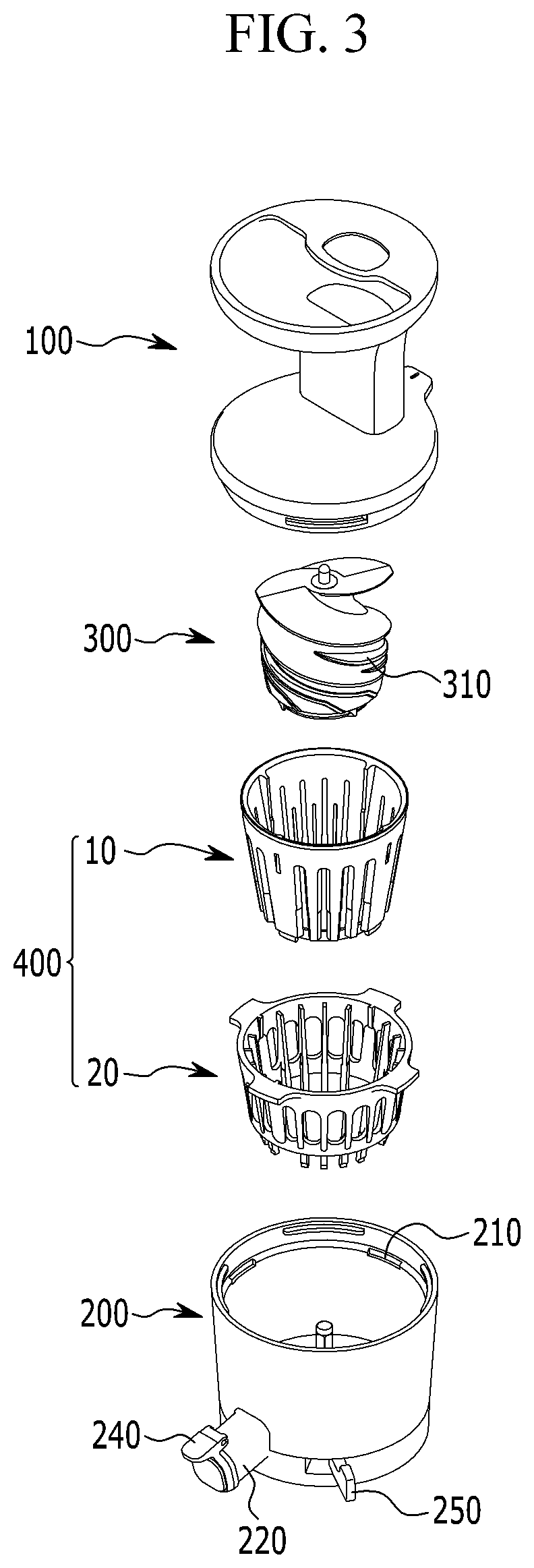
Juice extraction drum and juicer

a juice extraction drum and drum technology, applied in the field of juice, can solve the problems of difficult screw application to the juice extractor of a squeeze scheme, difficulty in cleaning the debris of the juice-extracting target on the mesh, and low juice-extracting efficiency, so as to achieve easy assembly and disassembly of the two modules, easy manufacturing, and easy cleaning

Pending Publication Date: 2021-04-29
HUROM CO LTD
View PDF0 Cites 2 Cited by
  • Summary
  • Abstract
  • Description
  • Claims
  • Application Information

AI Technical Summary

Benefits of technology

The present invention relates to a juice-extracting drum that has two modules that can be easily assembled and disassembled. The design allows for easy cleaning and smooth transfer of material during the squeezing process, resulting in increased efficiency of the juice-extracting process. The design also prevents debris from getting into the drum and improves the flow of the extracted juice. The use of a rigid material prevents deformation of the drum and maintains a constant interval between slits from which juice is discharged. The design also accurately fixes the combined position of the two modules and prevents rotation and tilting between them. The low-speed rotation of the screw and the squeezing and crushing method preserves the material's unique taste and nutrition.

Problems solved by technology

In the case of a juice-extracting drum having a mesh structure, there is a problem in that the juice-extracting efficiency is low because it is easily blocked by debris of the juice-extracting target during the juice-extracting process.
In addition, because the mesh is densely formed, there is a problem that cleaning to remove the debris of the juice-extracting target on the mesh may be difficult.
Although various other filter structures may be supposed, but it is difficult to be applied to a juice extractor of a squeezing scheme using a screw, because such merely performs a simple filtrate function.
However, if debris caught in netted holes is not fully removed, debris may decay and germs may propagate.
In a conventional netted drum structure, cleaning of debris stuck in netted holes is difficult.

Method used


Image

  • Juice extraction drum and juicer
  • Juice extraction drum and juicer
  • Juice extraction drum and juicer

Examples


Embodiment Construction

[0056]Hereinafter, exemplary embodiments of the present invention with reference to accompanying drawings. This specification is intended to describe the present invention in detail such that a person skilled in the art may easily implement the present invention, and it does not mean that the technical ideas and categories of the present invention are limited to the exemplary embodiments or descriptions disclosed in this specification.

[0057]In addition, since each component shown in drawings are illustrated for better understanding and ease of description, the present invention is not necessarily limited to that shown in the drawings, and a size or a shape of a constituent element shown in the drawings may be may be exaggerated for clarity of description and convenience. Therefore, terms specifically defined in consideration of the composition and operation of the present invention may vary depending on the user or operator's intention or convention, and the definition of such terms...


PUM


Abstract

A juice-extracting drum includes a screw rotating inside. An inner module includes a hollow cylinder with an upper portion having the screw. A plurality of slits are formed as penetration holes having both lateral sides, an upper surface, and a lower surface along an interior circumference. An outer module is detachably coupled to the inner module, and includes a rib protruding in a radially interior direction on an interior circumference. The rib is inserted into the slit of the inner module when the outer module surrounds and combines the inner module. A predetermined fixed gap discharging juice extracted by the screw is formed lengthily in an up and down direction between the lateral side of the slit of the inner module and a lateral side of the rib of the outer module. The fixed gap is formed in a direction intersecting the screw blade.

Description

CROSS-REFERENCE TO RELATED APPLICATION[0001]This application claims priority to and the benefit of Korean Patent Application No. 20-2018-0000605 filed in the Korean Intellectual Property Office on Feb. 7, 2018, the entire contents of which are incorporated herein by reference.BACKGROUND OF THE INVENTION(a) Field of the Invention[0002]The present invention relates to a juice-extracting drum used in a low-speed juice extractor and a juice extractor having the same. More particularly, the present invention relates to a juice-extracting drum having two modules and a juice extractor including the same.(b) Description of the Related Art[0003]In recent years, interest in health has been increasing in the home, and a use frequency of a juicer having a function of allowing juice to be taken from a juice-extracting target such as vegetables, grains, fruits, or the like, by an individual is increasing.[0004]A general mode of operation of such a juicer is a method in which a juice-extracting ta...

Claims


Application Information

Patent Timeline
Patent Type & Authority Applications(United States)
IPC IPC(8): A47J19/02A47J19/06B30B9/12B30B9/26B30B9/14
CPCA47J19/025A47J19/06B30B9/14B30B9/128B30B9/26B30B9/121A47J19/02A47J2201/00A47J19/027A23N1/02
Inventor KIMLEE, CHA WOO
Owner HUROM CO LTD
Learn More