Cooling element for use in a cooling device of a closed-circuit respirator

a technology of closed-circuit respirator and cooling element, which is applied in the direction of respirator, respiratory apparatus, life-saving device, etc., can solve the problems of affecting essentially an area, deformation of cooling element, and temperature range that is at least extremely uncomfortable for the user, and achieves robust use of cooling element and simple handling of cooling elemen

Active Publication Date: 2021-04-29
DRAGER SAFETY
View PDF5 Cites 0 Cited by
  • Summary
  • Abstract
  • Description
  • Claims
  • Application Information

AI Technical Summary

Benefits of technology

[0005]An object of the present invention is to make possible an especially simple handling of a cooling element, especially an especially robust use of a cooling element.

Problems solved by technology

In the closed breathing gas circuit, this leads over the duration of the use of the closed-circuit respirator to a rise in the temperature of the gas to be inhaled by the user of the closed-circuit respirator into a temperature range that is at least extremely uncomfortable for the user during the inhalation.
Furthermore, it was found that such problems caused by a deformation of the cooling element can be circumvented by this deformation taking place in a controlled manner, especially in a controlled manner without a change in the outer structure of the cooling element.
Thus, even though a change in the volume of the coolant ensures a deformation of the corresponding plate shape cooling element housing, this deformation affects essentially an area within the cooling element due to the arching of the two plate inner walls.
However, closed-circuit respirators are typically used in a comparatively narrow temperature range, e.g., between 0° C. and 50° C., so that such a great change in the volume of the coolant that this would cause a change in the plate outer walls in addition to a movement of the plate inner walls cannot typically occur.

Method used


Image

  • Cooling element for use in a cooling device of a closed-circuit respirator
  • Cooling element for use in a cooling device of a closed-circuit respirator
  • Cooling element for use in a cooling device of a closed-circuit respirator

Examples


Embodiment Construction

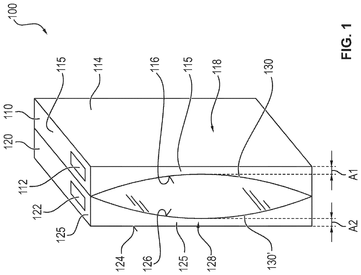
[0046]Referring to the drawings, FIG. 1 shows a schematic view of a first exemplary embodiment of a cooling element 100 according to the present invention.

[0047]The cooling element 100 is configured for use within a cooling device of a closed-circuit respirator and has a first plate shape cooling element housing 110 and a second late-like cooling element housing 120.

[0048]In the exemplary embodiment shown, both cooling element housings 110, 120 are made each in one part from a plastic. In particular, both cooling element housings 110, 120 are manufactured by a twin sheet process, in which two components are deep-drawn and then bonded or welded together.

[0049]The two cooling element housings 110, 120 have here a liquid-tight closure 112, 122 each and are filled or can be filled with a coolant (not shown).

[0050]In the exemplary embodiment shown, the liquid-tight closure 112, 122 is a non-detachable, permanent closure, namely, a welded opening, through which the coolant, in this case w...


PUM


Abstract

A cooling element (100) for use within a cooling device (600) of a closed-circuit respirator (690), includes a plate shaped cooling element housings (110, 120), each with a respective liquid-tight closure (112, 122) filled or to be filled with a coolant (211). The cooling element housings (110, 120) each have a plate outer wall (114, 124) and a plate inner wall (116, 126) arched in the direction of the plate outer wall, which form, together with additional side walls (115, 125), cooling element volumes (118, 128) for the coolant. The plate shape cooling housings can be fastened or are fastened to each other such that the one plate inner wall and another plate inner wall are located opposite each other and are arched away from one another.

Description

CROSS REFERENCE TO RELATED APPLICATIONS[0001]This application claims the benefit of priority under 35 U.S.C. § 119 of German Application 10 2019 007 408.4, filed Oct. 24, 2019, the entire contents of which are incorporated herein by reference.TECHNICAL FIELD[0002]The present invention pertains to a cooling element for use within a cooling device of a closed-circuit respirator. The present invention pertains, furthermore, to a cooling device for a closed-circuit respirator and to a closed-circuit respirator.TECHNICAL BACKGROUND[0003]The use of a cooling device in a closed-circuit respirator for cooling a breathing gas stream is known and necessary. Thus, a lime, which is typically used as an absorbent for gas treatment, and which treats the breathing gas by removing CO2, produces heat continuously. In the closed breathing gas circuit, this leads over the duration of the use of the closed-circuit respirator to a rise in the temperature of the gas to be inhaled by the user of the close...

Claims


Application Information

Patent Timeline
Patent Type & Authority Applications(United States)
IPC IPC(8): A62B9/00
CPCA62B9/003A61M16/0003
Inventor HAYRAN, UGUR
Owner DRAGER SAFETY
Why Eureka
Try Eureka