
Torque transmission system having multiple torque transmission pathways from a driving shaft to a driven shaft, and a vehicle

a transmission system and torque technology, applied in the direction of couplings, transportation and packaging, gearing, etc., can solve the problems of system jamming, driving shaft misalignment relative to the axis of rotation, etc., and achieve the effect of limiting the risk of jamming

Active Publication Date: 2021-05-06
EUROCOPTER
View PDF0 Cites 0 Cited by
  • Summary
  • Abstract
  • Description
  • Claims
  • Application Information

AI Technical Summary

Benefits of technology

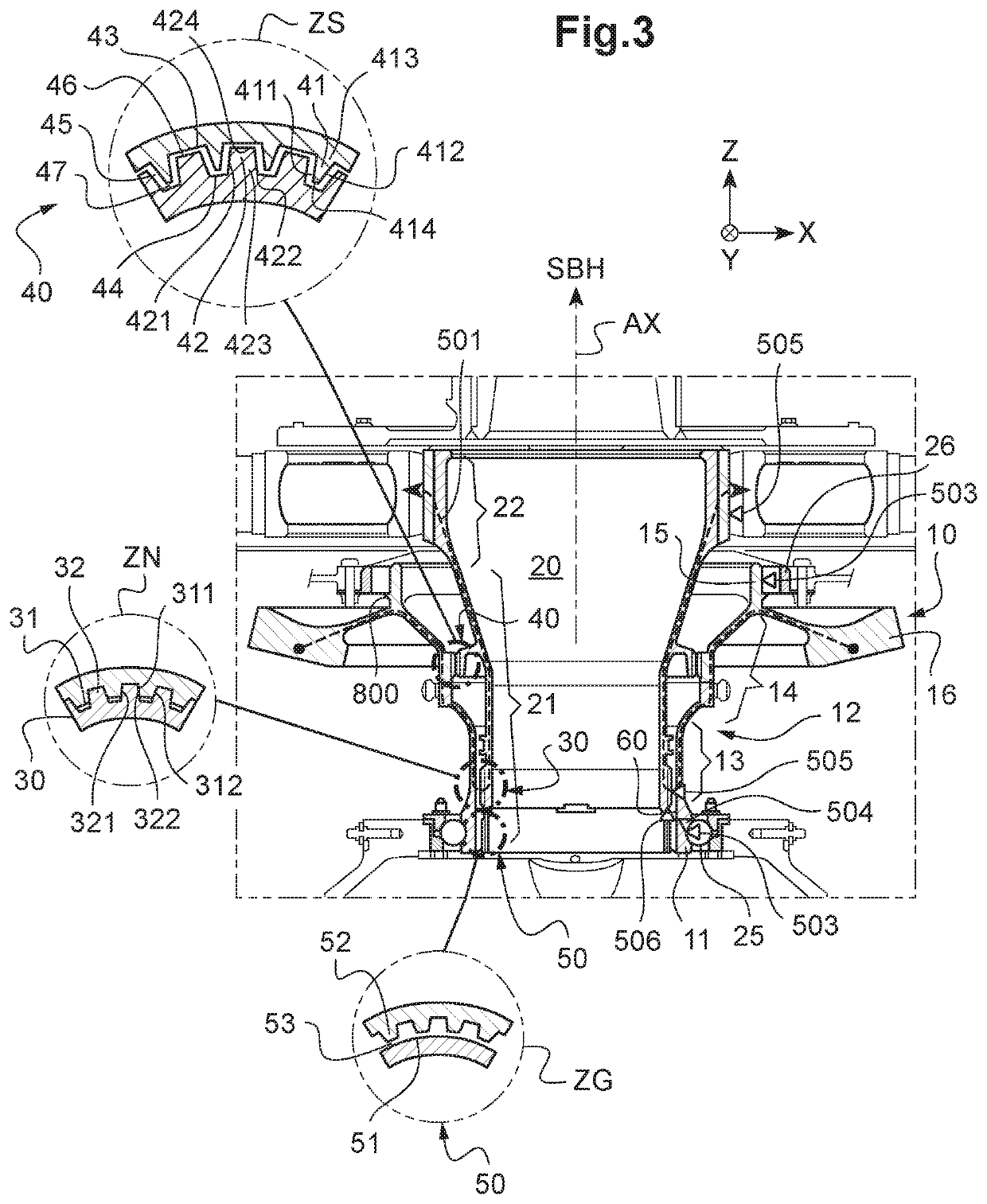
The present invention proposes an alternative torque transmission system to avoid risks of jamming caused by breakages. The system includes a driving shaft, a lower bearing, an upper bearing, and a backup spline coupling. The driving shaft transmits torque to the driven shaft through the spline coupling and the backup spline coupling is inactive in the normal operating mode to avoid multiple torque transmission points. This characteristic helps to keep the loads under control and avoids statically indeterminate situations and degradation of the backup spline coupling. The backup radial guide device also plays a role in ensuring proper operation of the system in the event of a breakage. The system has a small gap to prevent contact between the backup splines during the normal operating mode and can detect any misalignments or degraded operating mode through the gaps. The backup radial guide device has multiple guide splines that do not serve to transmit torque.

Problems solved by technology

However, accidental breakage of a bearing or of one of the segments of the driving shaft co-operating with a bearing can result in the driving shaft becoming misaligned relative to the axis of rotation, and in the system jamming.

Method used


Image

  • Torque transmission system having multiple torque transmission pathways from a driving shaft to a driven shaft, and a vehicle
  • Torque transmission system having multiple torque transmission pathways from a driving shaft to a driven shaft, and a vehicle
  • Torque transmission system having multiple torque transmission pathways from a driving shaft to a driven shaft, and a vehicle

Examples


Embodiment Construction

[0066]Elements present in more than one of the figures are given the same references in each of them.

[0067]Three mutually orthogonal axes X, Y, and Z are shown in some of the figures.

[0068]The third axis Z is said to be “longitudinal”. The term “longitudinal” and the term “axial”, or indeed the expression “in elevation” are relative to any axis parallel to the first axis X.

[0069]The second axis Y and the first axis X are said to be “radial in elevation”. The term “radial” is relative to any axis orthogonal to the first axis X.

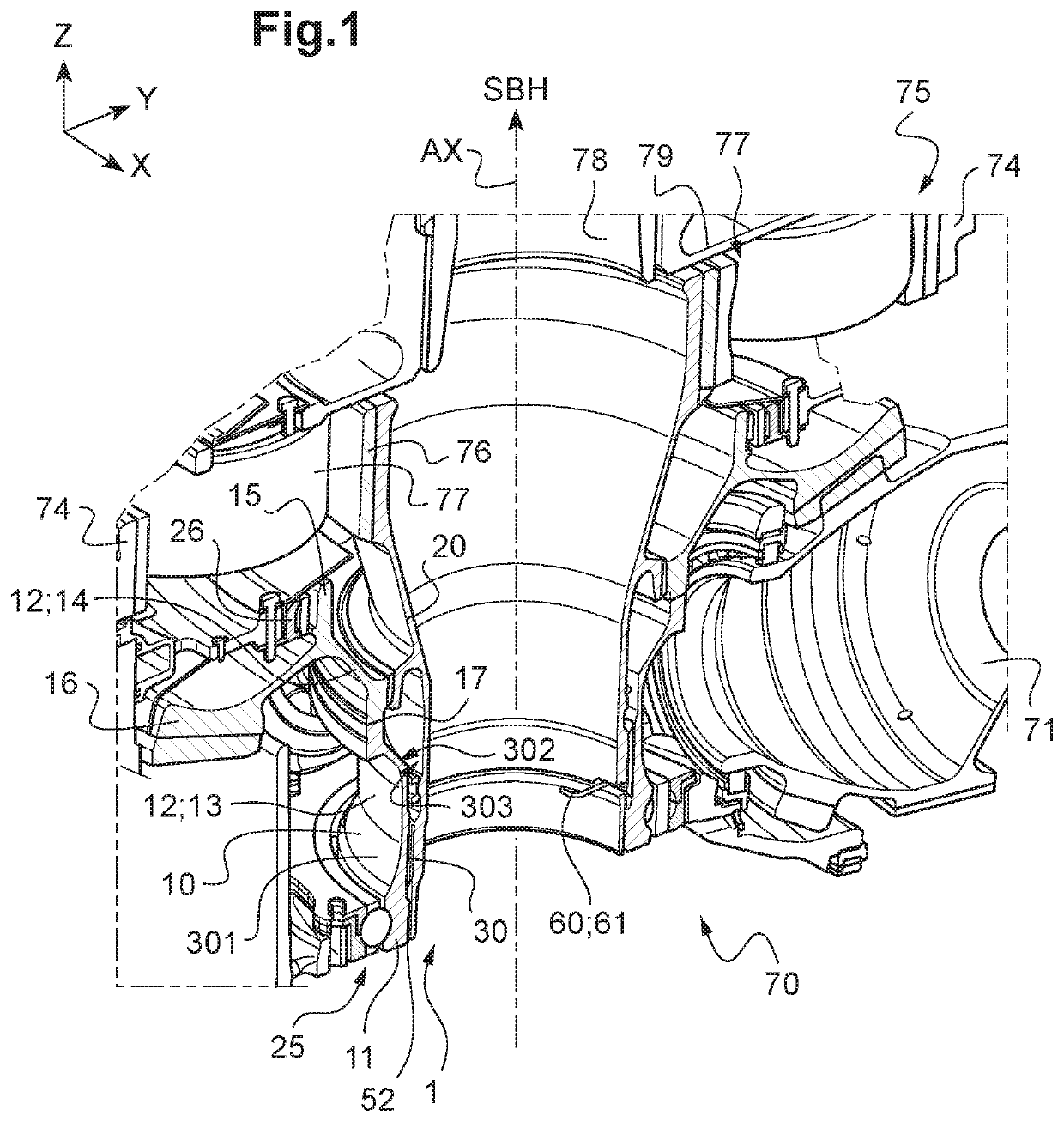
[0070]FIG. 1 shows a torque transmission system 1 of the invention having multiple torque transmission pathways.

[0071]This transmission system 1 has a driving shaft 10 and a driven shaft 20 that are both mounted to move in rotation about an axis of rotation AX under normal conditions. The driving shaft 10 is connected to the driven shaft 20 via multiple couplings.

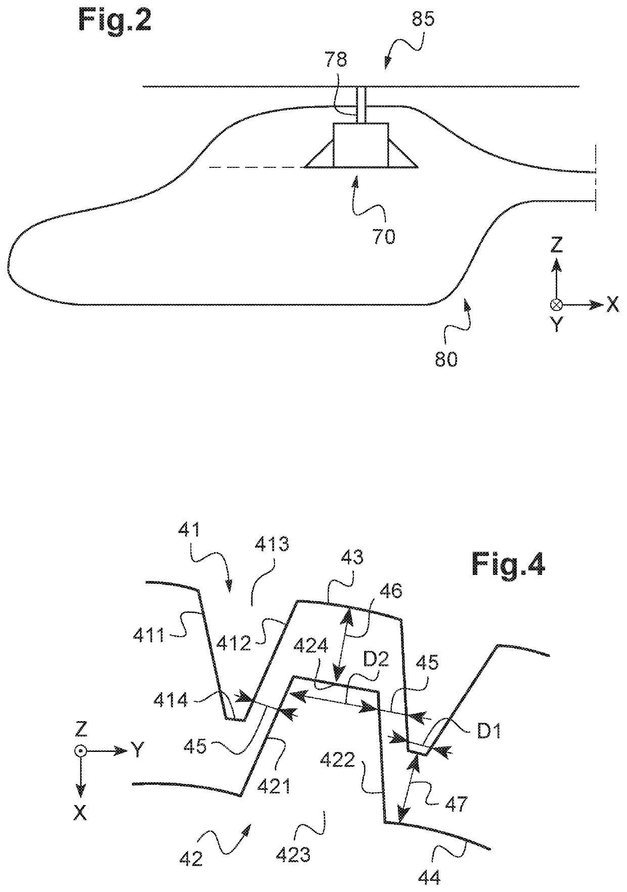
[0072]As shown in FIG. 1, the transmission system 1 may be arranged in a main gearbox 70. For examp...


PUM


Abstract

A torque transmission system having multiple torque transmission pathways from a driving shaft to a driven shaft. The driving shaft extends from a lower segment to an upper segment via an intermediate segment, the driven shaft extending from a first segment to a second segment. The transmission system includes a nominal spline coupling that is operational in a nominal operating mode, a backup spline coupling between the driving shaft and the driven shaft that is inactive in the nominal operating mode, and a backup radial guide device between the driving shaft and the driven shaft that is inactive in the nominal operating mode.

Description

CROSS-REFERENCE TO RELATED APPLICATIONS[0001]This application claims priority to French patent application No. FR 1912204 filed on Oct. 30, 2019, the disclosure of which is incorporated in its entirety by reference herein.BACKGROUND OF THE INVENTION(1) Field of the Invention[0002]The present invention relates to a torque transmission system having multiple torque transmission pathways from a driving shaft to a driven shaft, and also relates to a vehicle including such a system. The vehicle may be an aircraft and optionally a rotorcraft.(2) Description of Related Art[0003]For example, a rotorcraft may include a power transmission main gearbox for causing a lift rotor to move in rotation by means of at least one engine or motor. The main gearbox is provided with a system making it possible to transfer movement from a rotary driving member to a rotary driven member.[0004]In an example, a main gearbox has at least one inlet gear, each inlet gear being connected via a mechanical drive sy...

Claims


Application Information

Patent Timeline
IPC IPC(8): B64D35/00B64C27/12F16D9/08
CPCB64D35/00F16D2001/103F16D9/08B64C27/12F16D9/10F16D1/10F16H2057/0081F16H35/10F16D3/185
Inventor GOUJET, DAMIEN
Owner EUROCOPTER
Learn More