

Laundry treating appliance with a filter
- Summary
- Abstract
- Description
- Claims
- Application Information
AI Technical Summary
Benefits of technology
Problems solved by technology
Method used
Image

Examples
Embodiment Construction
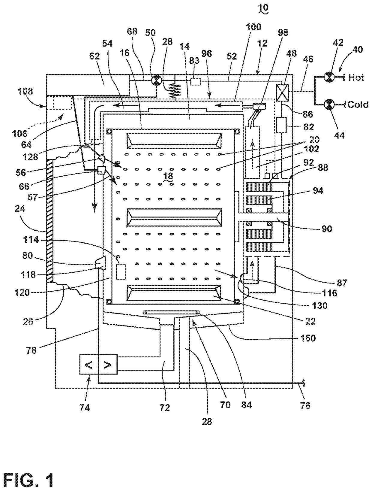
[0023]Aspects of the present disclosure relate to a filter disposes at an inlet of a drying air duct. The drying air duct can be a recirculation duct which can recirculate the air back into the drum, or it can be an air duct which leads to an exterior portion of the laundry treating appliance. The filter can be used in any type of laundry treating appliance needing to dry laundry, such laundry treating appliances can be a clothes dryer or a combination washer / dryer (combo).
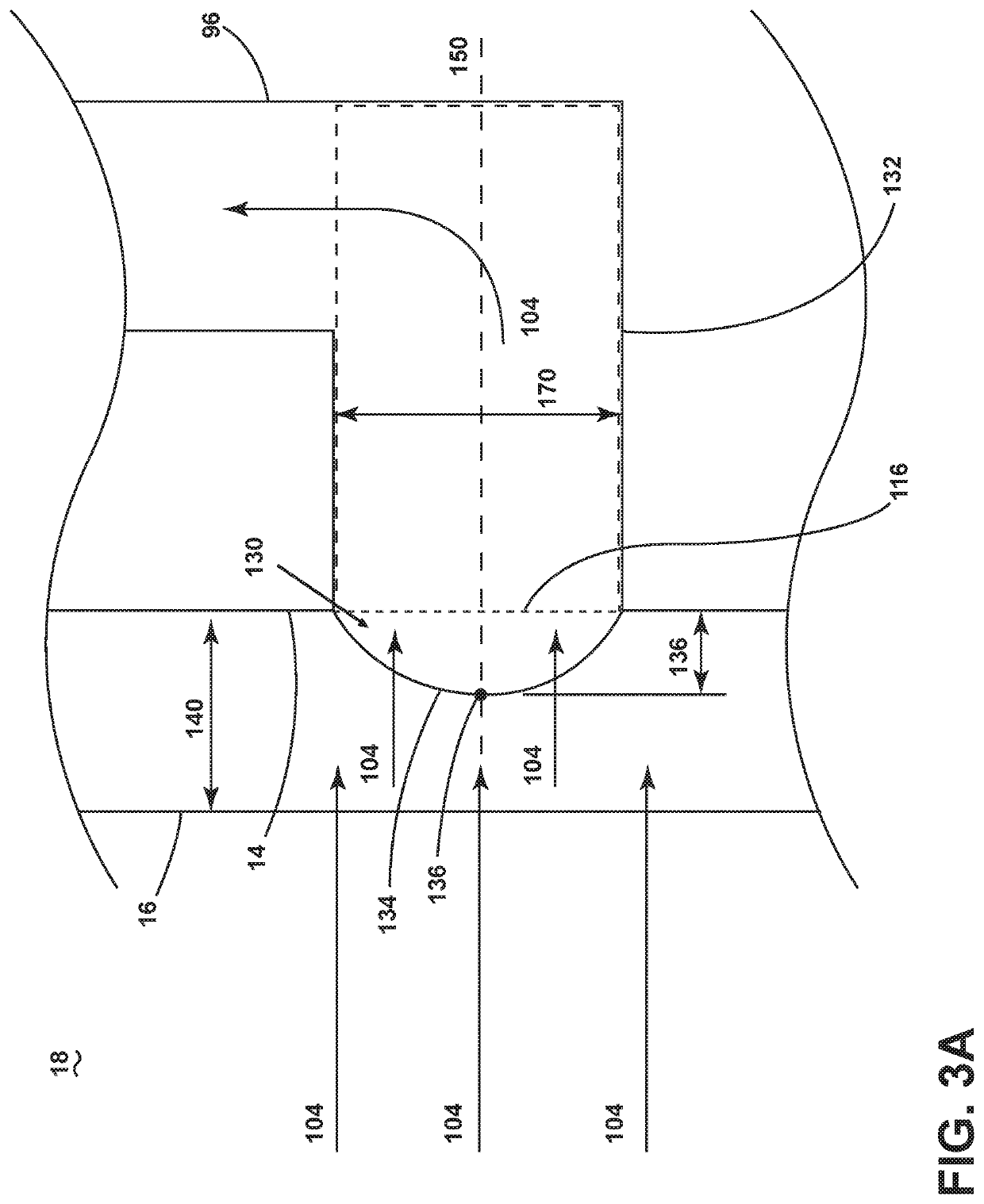
[0024]In traditional combination washing and drying machines, drying air can be delivered to the tub interior near a bellows in a radial direction. However, this can result in an excess of lint building being built up around a chassis opening of the laundry treating appliance. The present disclosure sets forth a laundry treating appliance having an annular bellows that can direct drying air through a deflection component, which in turn can induce at least a portion of the drying air into a circumferential airflow....
PUM
| Property | Measurement | Unit |
|---|---|---|
| Length | aaaaa | aaaaa |
| Area | aaaaa | aaaaa |
| Surface area | aaaaa | aaaaa |
Abstract
Description
Claims
Application Information