Telescopic ladder rod unit

Pending Publication Date: 2021-05-27
DONGGUAN CASA HOUSEWARES CO LTD
View PDF0 Cites 0 Cited by
  • Summary
  • Abstract
  • Description
  • Claims
  • Application Information

AI Technical Summary

Benefits of technology

The patent describes a telescopic ladder that has a unique design to ensure safety and ease of use. When the ladder is retracted, air pressure pushes a movable plug to move upward and block an air vent, creating a cushioning effect to prevent injury to the operator's hands. On the other hand, when the ladder is extended, external pressure pushes the movable plug downward, allowing air to quickly enter the ladder's air chamber and making it convenient to use. Overall, the design of the telescopic ladder helps to achieve high safety performance and provides a comfortable and convenient user experience.

Problems solved by technology

However, considering that in actual practice, in a process of manually retracting the telescopic ladder, since the telescopic ladder has no buffering effect, the telescopic ladder itself also has a certain weight and an operator has to forcefully retract the telescopic ladder, it is difficult to ensure the retraction strength during the retracting process, which would cause the telescopic ladder to be retracted quickly, so that the operator is easy to pinch her / his hands when retracting the telescopic ladder, the safety performance is low, and therefore it needs to be improved.

Method used


Image

  • Telescopic ladder rod unit
  • Telescopic ladder rod unit
  • Telescopic ladder rod unit

Examples


Embodiment Construction

[0017]The invention will be described below in detail with reference to the accompanying drawings.

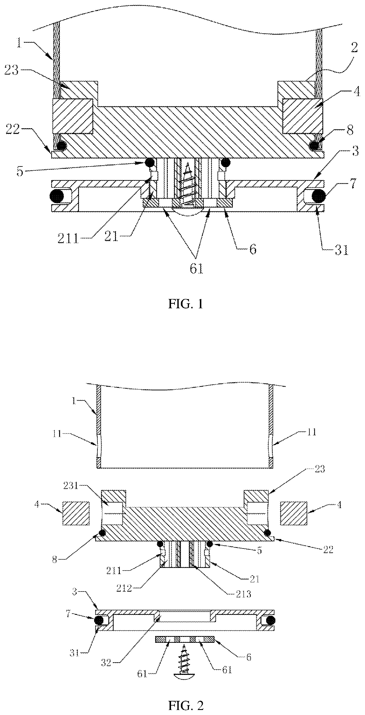
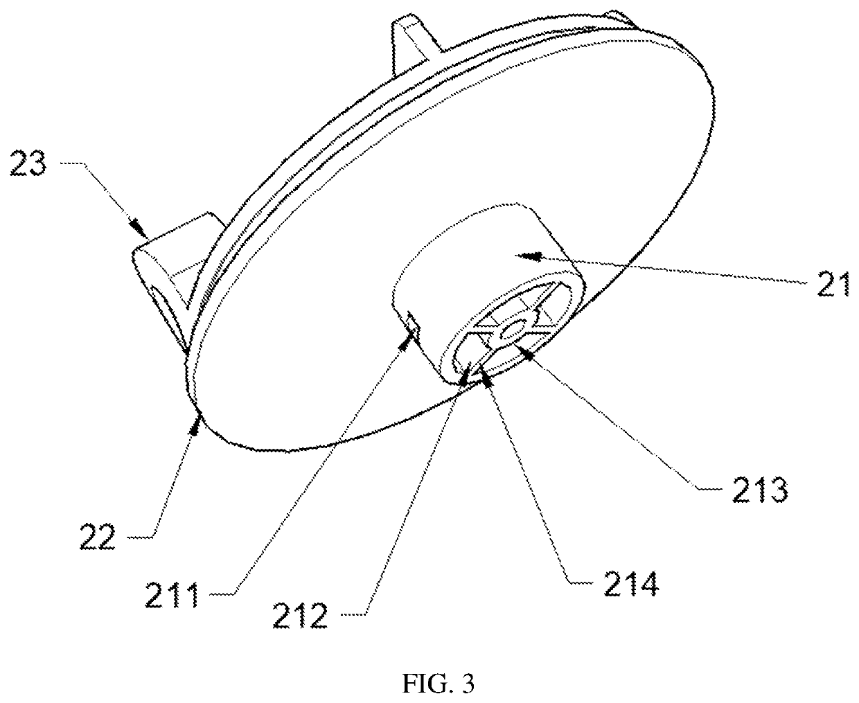
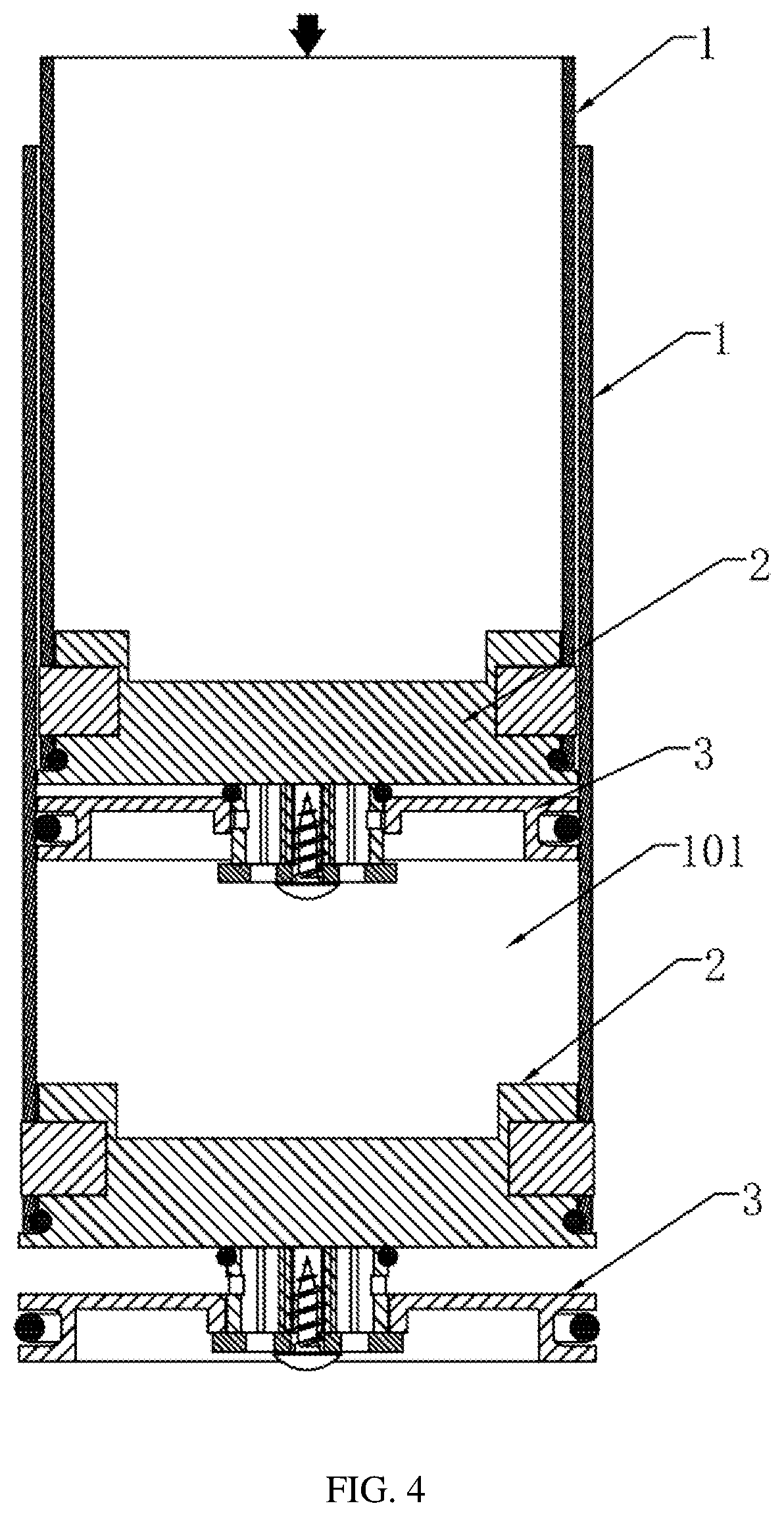
[0018]Referring to FIGS. 1-5, a telescopic ladder rod unit (also referred to as rod unit of a telescopic ladder) includes an air cylinder (also referred to as air-filled cylindrical body) 1, a fixing seat 2 and a movable plug 3. The fixing seat 2 is fixedly connected to a bottom of the air cylinder 1 by a connector (also referred to as connection piece) 4. A bottom of the fixing seat 2 is disposed with a first mounting portion 21 protruding therefrom downwardly. An upper end of the first mounting portion 21 is sleeved with a first sealing ring 5. A sidewall of the first mounting portion 21 below the first sealing ring 5 is formed with at least one first air vent 211. An air passage 212 is formed in the first mounting portion 21 and communicated with the first air vent 211. A blocking plate 6 is fixed at a bottom of the first mounting portion 21. The blocking plate 6 is formed with at le...


PUM


Abstract

A telescopic ladder rod unit includes an air cylinder, a fixing seat and a movable plug. The fixing seat is connected to the air cylinder by a connector. A bottom of the fixing seat is disposed with a first mounting portion protruding downwardly. An upper end of the first mounting portion is sleeved with a first sealing ring. A sidewall of the first mounting portion below the first sealing ring is formed with a first air vent. An air passage communicated with the first air vent is disposed in the first mounting portion. A blocking plate is fixed at a lower end of the first mounting portion and formed with a second air vent communicated with the air passage. The movable plug is movably sleeved on the first mounting portion. A sidewall of the movable plug is formed with a first annular groove having a second sealing ring mounted therein.

Description

TECHNICAL FIELD[0001]The invention relates to the field of telescopic ladder technologies, and more particularly to a telescopic ladder rod unit with cushioning / buffering function.DESCRIPTION OF RELATED ART[0002]A telescopic ladder generally is formed by a multi-section left ladder rod, a multi-section right ladder rod, and horizontal plates connected between the left ladder rod and the right ladder rod. A conventional telescopic ladder has no buffering effect when it is retracted, and the ladder rods would be extended and retracted quickly. However, considering that in actual practice, in a process of manually retracting the telescopic ladder, since the telescopic ladder has no buffering effect, the telescopic ladder itself also has a certain weight and an operator has to forcefully retract the telescopic ladder, it is difficult to ensure the retraction strength during the retracting process, which would cause the telescopic ladder to be retracted quickly, so that the operator is e...

Claims


Application Information

Patent Timeline
IPC IPC(8): E06C1/12
CPCE06C1/125
Inventor JIN, ZHULIN, SHUYUAN
Owner DONGGUAN CASA HOUSEWARES CO LTD
Why Eureka
Try Eureka