
Apparatus for zygomatic implantation and method

a technology of zygomatic implantation and apparatus, which is applied in the field of dental implants, can solve the problems of damage to organs hit by drills and damage that is sometimes irreparable, and achieve the effects of reducing the number of dental procedures

Pending Publication Date: 2021-06-17
NORIS MEDICAL LTD
View PDF0 Cites 0 Cited by
  • Summary
  • Abstract
  • Description
  • Claims
  • Application Information

AI Technical Summary

Benefits of technology

The invention is a dental implantation guide that ensures the implant is inserted in the correct position without causing complications to other organs in the skull. It is easy to use and can be produced by manufacturers or dental laboratories. The guide helps to make the dental procedure safer and simpler, and reduces the duration of the intervention.

Problems solved by technology

One problem with prior art zygomatic implants is that a dentist must correctly guide and operate a free hand-held drill rotating osteomatic device, such as a drill rotated by a handpiece, to drill in a precise direction into a bone of the skull, which bone may be hidden from view, along a predetermined oriented direction.
It has to be considered that straying from the desired predetermined oriented direction may damage organs hit by the drill.
Such damage is sometimes irreparable.

Method used


Image

  • Apparatus for zygomatic implantation and method
  • Apparatus for zygomatic implantation and method
  • Apparatus for zygomatic implantation and method

Examples


Embodiment Construction

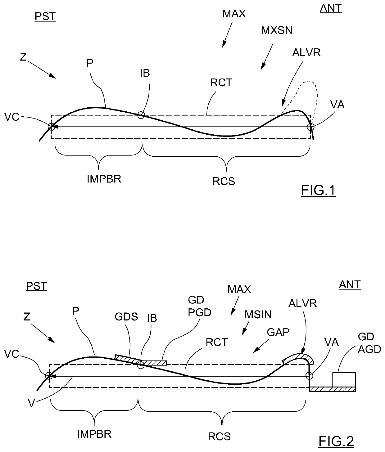
[0038]FIG. 1 is an illustration used for the sake of orientation and ease of description.

[0039]FIG. 1 schematically depicts the shape of a profile line P of a cross-section taken through the naked maxilla bone MAX, thus from which tissue has been folded-over or removed. The profile line P is disposed in a plane cut through the axis of an implantation bore IMPBR opened for implanting therein of an extra maxillary zygomatic implant ZI coinciding with a planned implantation vector V selected by a dentist. The implantation vector V, or vector V of implantation, may pass from the anterior ANT alveolar ridge ALVR, via the maxillary sinus MXSN to the posterior PST zygomatic bone Z. Such a profile line P for a particular person may be obtained by use of CAD / CAM computer programs operated on images derived by three-dimensional imaging facilities. The dashed-line rectangle RCT superimposed on the profile line P represents a cross-section cut in the plane of the profile P, of a cylinder envelo...


PUM


Abstract

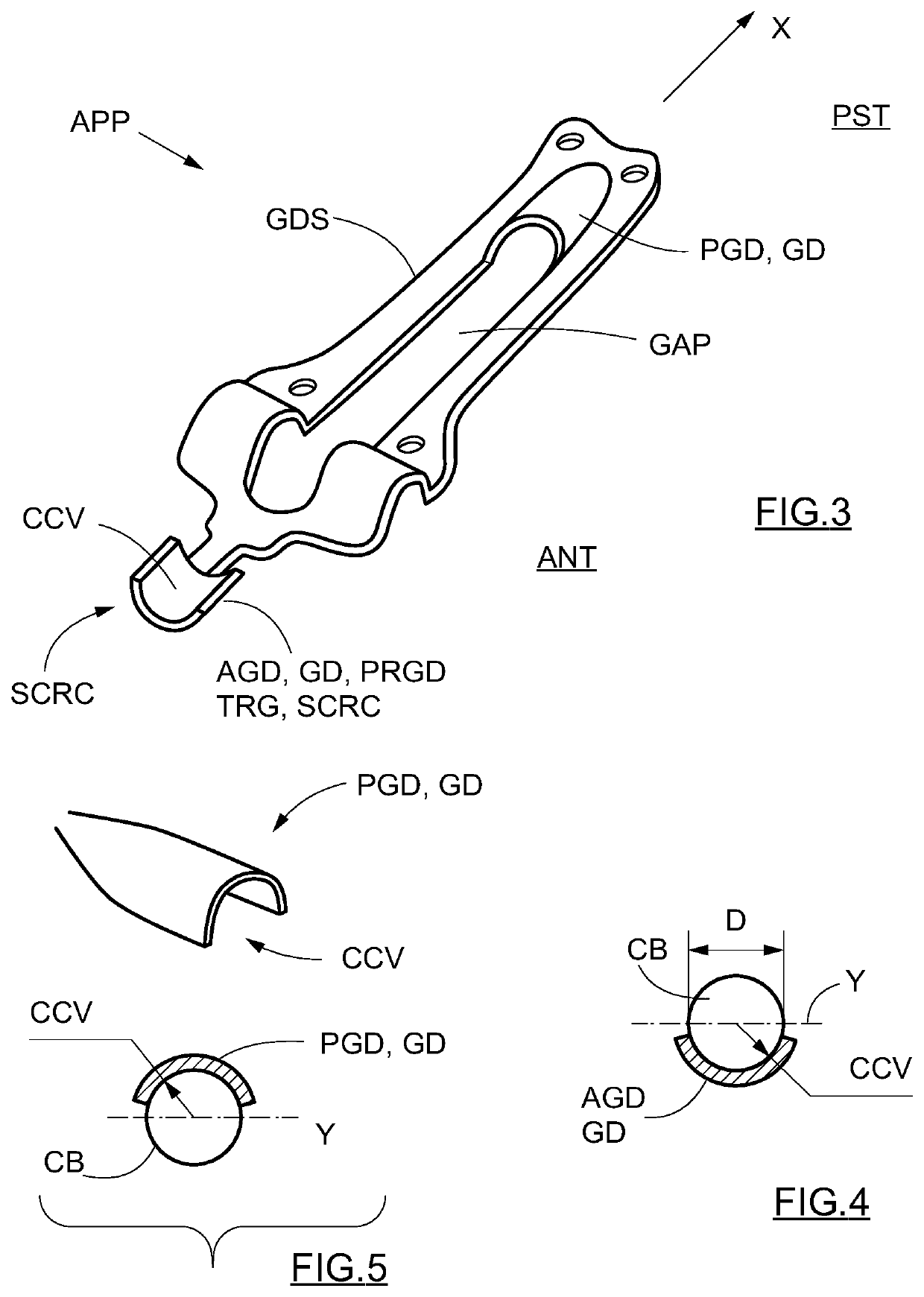
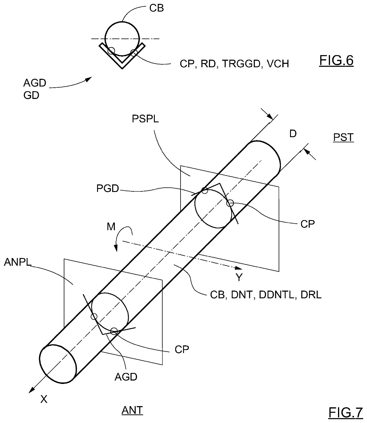
An apparatus for implantation of a zygomatic implant in coincidence with an implantation vector includes a dedicated dental tool and a dental implantation guide including a guide shell configured to conform to and to be releasably affixed to a portion of a maxillary bone. The guide shell supports a plurality of guides including an anterior guide and a posterior guide which together form a pair of guides that are distanced apart relative to each other, are configured to be aligned with the implantation vector, and are configured as concave troughs for support of a cylindrical body, the cylindrical body being at least one of the zygomatic implant, the dedicated dental tool, an implantation drill, and a preliminary drill.

Description

CROSS-REFERENCE TO RELATED APPLICATIONS[0001]The present application is a Continuation of International Patent Application No. PCT / IL2019 / 050956, filed Aug. 27, 2019, and claims the benefit of priority of Israeli Patent Application No. 261494, filed Aug. 30, 2018, the entire contents of both of which are incorporated herein by reference.TECHNICAL FIELD[0002]The embodiments described hereinbelow relate to the field of implantation of dental implants, and in particular to apparatus and methods for guidance and implantation of extra maxillary and intra maxillary sinus zygomatic implants.DESCRIPTION OF RELATED ART[0003]Zygomatic implants are well known for years as dental implants for the upper jaw, or maxilla.[0004]One problem with prior art zygomatic implants is that a dentist must correctly guide and operate a free hand-held drill rotating osteomatic device, such as a drill rotated by a handpiece, to drill in a precise direction into a bone of the skull, which bone may be hidden from...

Claims


Application Information

Patent Timeline
Patent Type & Authority Applications(United States)
IPC IPC(8): A61C8/00A61C1/08B33Y80/00
CPCA61C8/0034B33Y80/00A61C1/084A61C8/0089A61C1/082A61C8/0092
Inventor SIEV, AHARONSIEV, RAMI
Owner NORIS MEDICAL LTD
Learn More