Electrode forming method

a technology of electrodes and forming methods, applied in the direction of liquid/solution decomposition chemical coating, paper/cardboard containers, transportation and packaging, etc., can solve the problems of difficult to obtain a large electrode surface area and several days of production, and achieve the reduction of the number of steps required for forming an electrode layer, the effect of reducing the number of steps

Inactive Publication Date: 2011-04-14
EAMEX
View PDF7 Cites 0 Cited by
  • Summary
  • Abstract
  • Description
  • Claims
  • Application Information

AI Technical Summary

Benefits of technology

[0007]An electrode forming method of the invention of the application is directed to an electrode forming method, in which a metal salt solution and a reducing agent solution are disposed on respective both sides of a solid electrolyte form and the metal salt solution is caused to pass through the solid electrolyte molded product by osmosis to thereby deposit a metal near the interface on the reducing agent solution side of the solid electrolyte molded product and an electrode is formed in the solid electrolyte form. With the electrode forming method adopted, it is possible to obtain an electrode layer having a large electrode surface area and adsorption and reduction of a metal complex can be simultaneously performed in parallel to each other, thereby enabling the number of steps required for forming the electrode layer to be decreased.
[0008]According to the invention of the application, the solid electrolyte form is a tubular or cylindrical solid electrolyte form and that the metal salt solution is caused to pass through the solid electrolyte form by osmosis is also an electrode forming method performed in either of a step (1) or a step (2) mentioned below. In the step (1), the solid electrolyte form is immersed in the reducing agent solution so that the outer side surface of the solid electrolyte form is in contact with the reducing agent solution and the metal salt solution is caused to flow in a space on the inner side of the solid electrolyte form to cause the metal salt solution to pass through the solid electrolyte form by osmosis to thereby deposit a metal on the outer side surface of the solid electrolyte form. In the step (2), the solid electrolyte form is immersed in the metal salt solution so that the outer side surface of the solid electrolyte form is in contact with the metal salt solution and the reducing agent solution is caused to flow in a space on the inner side of the solid electrolyte form to thereby cause the metal salt solution to pass through the solid electrolyte form by osmosis to thereby deposit a metal on the inner side surface of the solid electrolyte form. With the electrode forming method adopted, a metal salt or a reducing agent consumed in deposition of the metal on the outer side surface or inner side surface of a tubular or cylindrical solid electrolyte form can be supplied into the interior of the tube without interruption, thereby enabling an electrode layer having a large electrode surface area to be obtained without strictly adjusting a concentration of the metal salt solution or the reducing agent solution. Since the electrode forming method enables adsorption and reduction of a meal complex to be simultaneously performed in parallel to each other, the number of steps required for forming an electrode layer can be reduced, thereby enabling an electrode to be formed with simplicity and ease.

Problems solved by technology

However, in order to obtain an actuator having a large electrode surface area, since a necessity arises for forming an electrode with an electrode forming method using the electroless plating, it takes several days in production because of repetition of the pair of an adsorption step and a reduction step.
The method is suited for obtaining an electrode with a uniform thickness, whereas it is difficult to obtain a large electrode surface area, thereby disabling an actuator large in bending or displacement and having a large electrode surface area as mentioned above to be obtained.

Method used


Image

  • Electrode forming method
  • Electrode forming method
  • Electrode forming method

Examples


example 1

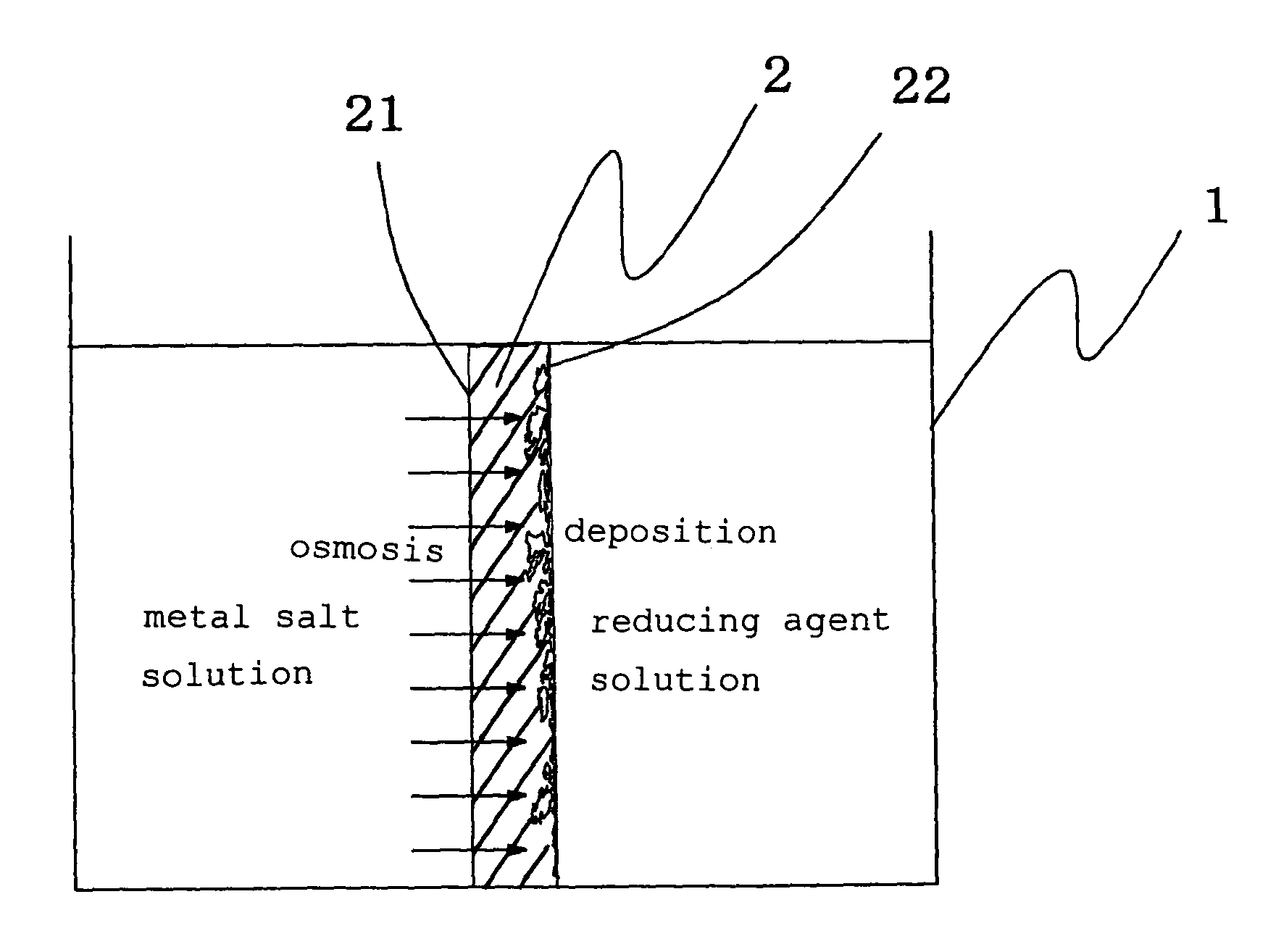
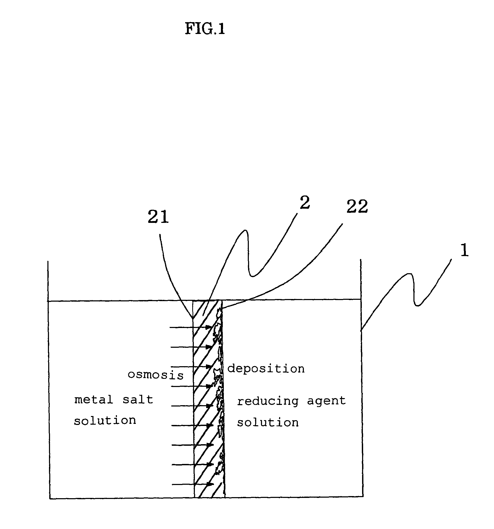
[0049]A film-like fluororesin-based ion exchange resin form with a film thickness of 200 μm (trade name: Flemion, made from perfluorocarboxylic acid resin and manufactured by Asahi Glass Co., Ltd. with an ion exchange capacity of 1.44 meq / g) was used as a solid electrolyte form, both surfaces of the ion exchange resin molded product film were roughened using alumina particles having a grain size of #800, and thereafter the ion exchange resin molded product was placed in a known plastic vessel in the shape of a box open at the top thereof so that the ion exchange resin molded product working as a partition in the plastic vessel, wherein a space on one side of the partition was filled with a dichlorophenanthroline gold aqueous solution (with a concentration of 1.0 wt %), while a space on the other side was filled with a sodium sulfite aqueous solution (with a concentration of 5 wt %). The dichlorophenanthroline gold aqueous solution was kept at a temperature higher than the sodium sul...

example 2

[0050]An actuator element of Example 2 was obtained in a similar way to that in Example 1 with the exception that in Example 2, a fluororesin-based ion exchange resin molded product with an ion exchange capacity of 1.80 meq / g (trade name: Flemion, made from perfluorocarboxylic acid resin and manufactured by Asahi Glass Co., Ltd.) was used instead of the fluororesin-based ion exchange resin molded product with an ion exchange capacity of 1.44 meq / g (trade name: Flemion, made from perfluorocarboxylic acid resin and manufactured by Asahi Glass Co., Ltd.).

example 3

[0051]A fluororesin-based ion exchange resin (trade name: Flemion, made from perfluorocarboxylic acid resin and manufactured by Asahi Glass Co., Ltd. with an ion exchange capacity of 1.44 meq / g) was molded into a tube by means of an extrusion molding method to thereby obtain a perfluorocarboxylic acid tube (with an ion exchange capacity of 1.44 meq / g, an inner diameter of 0.57 mm and an outer diameter of 0.65 mm), plastic tubes (made from silicone) with the same inner diameter and the same outer diameter as the perfluorocarboxylic acid tube were attached to both ends of the perfluorocarboxylic acid tube and the perfluorocarboxylic acid tube was immersed in a sodium sulfite aqueous solution (having a concentration of 10 wt %) with which a known glass vessel in the shape of a box open at the top thereof was filled. The dichlorophenanthroline gold aqueous solution (having a concentration of 1.0 wt %) was poured into one tube made from silicone attached to the perfluorocarboxylic acid t...


PUM

PropertyMeasurementUnit
thicknessaaaaaaaaaa
thicknessaaaaaaaaaa
temperaturesaaaaaaaaaa

Abstract

The present invention provides an electrode forming method in which an electrode layer is formed on a solid electrolyte, capable of obtaining an electrode layer having a large electrode surface area, decreasing the number of steps required in formation of the electrode layer and reducing a human labor and time. The electrode forming method of the invention is an electrode forming method, in which a metal salt solution and a reducing agent solution are disposed on respective both sides of a solid electrolyte form and the metal salt solution is caused to pass through the solid electrolyte form by osmosis to thereby deposit a metal near the interface on the reducing agent solution side of the solid electrolyte form to thereby form the electrode on the solid electrolyte form.

Description

CROSS-REFERENCE TO RELATED APPLICATIONS[0001]This application is a divisional of U.S. application Ser. No. 10 / 525,202, filed on Apr. 14, 2006, which is a 371 of International Application No. PCT / JP2003 / 10679 filed on Aug. 25, 2003, which is based upon and claims the benefit of priority from prior Japanese Patent Application No. 2002-311696, filed on Oct. 25, 2002 and Japanese Patent Application No. 2002-244196, filed on Aug. 23, 2002, the entire contents of which are incorporated herein by reference.TECHNICAL FIELD[0002]The present invention relates to an electrode forming method for forming an electrode near a surface of a solid electrolyte and a producing method of an actuator in which an electrode is formed using the electrode forming method.BACKGROUND ART[0003]An actuator capable of bending and displacement, particularly a polymer actuator, has been employed as a driving part of a catheter or the like because of its flexibility. The actuator can be used as an actuator that is co...

Claims


Application Information

Patent Timeline
Patent Type & Authority Applications(United States)
IPC IPC(8): B05D5/12B31B1/60C23C18/16C23C18/31C23C26/02
CPCC23C18/1648C23C18/1658Y10T156/10C23C18/31C23C26/02C23C18/166
Inventor ONISHI, KAZUOSEWA, SHINGO
Owner EAMEX
Why Eureka
Try Eureka