Positive and negative wind pressure automatic cleaning method for optical device

an automatic cleaning and optical device technology, applied in the direction of cleaning process and apparatus, instruments, chemistry apparatus and processes, etc., can solve the problems of increasing the complexity of the structure, and the inability to automatically clean the dust accumulation on the cover, so as to facilitate the removal, the effect of less attachment and easy cleaning

Active Publication Date: 2021-06-17
NANJING TURBINE POWER CONTROL CO LTD
View PDF0 Cites 0 Cited by
  • Summary
  • Abstract
  • Description
  • Claims
  • Application Information

AI Technical Summary

Benefits of technology

[0012]Compared with the prior art, the invention has the following remarkable advantages.
[0013]1. According to the invention, automatic cleaning of the surface of the optical element and device is realized, and the problems that the rotor grounding detection precision, sensitivity and reliability are influenced due to dust accumulation are solved.
[0014]2. For the original accumulated dust or dust particles on the surface of the optical device, repeated high-speed vibration can loosen the adhesion of the accumulated dust or dust particles, and the accumulated dust or dust particles can be more easily carried away by the wind.
[0015]3. For new dust particles coming along with wind, the surfaces of the new dust particles are under a force in alternating positive and negative directions, so that the new dust particles are less easily attached to the surface of an element, and the surface is kept clean for a long time.
[0016]4. According to the invention, a transparent or semi-transparent casing is not needed so that the loss of light on the casing is reduced. The utilization rate of an optical signal is improved, the loss power of an optical device is reduced, the service life of the optical device is prolonged, and the sensitivity and the reliability of rotor grounding detection are increased.

Problems solved by technology

But on one hand, the method increases the complexity of the structure and on the other hand the dust accumulation on the cover cannot be automatically cleaned such that when the time is long, the accuracy and the sensitivity of the detection of the optical device are still influenced.

Method used


Image

  • Positive and negative wind pressure automatic cleaning method for optical device
  • Positive and negative wind pressure automatic cleaning method for optical device
  • Positive and negative wind pressure automatic cleaning method for optical device

Examples


embodiment

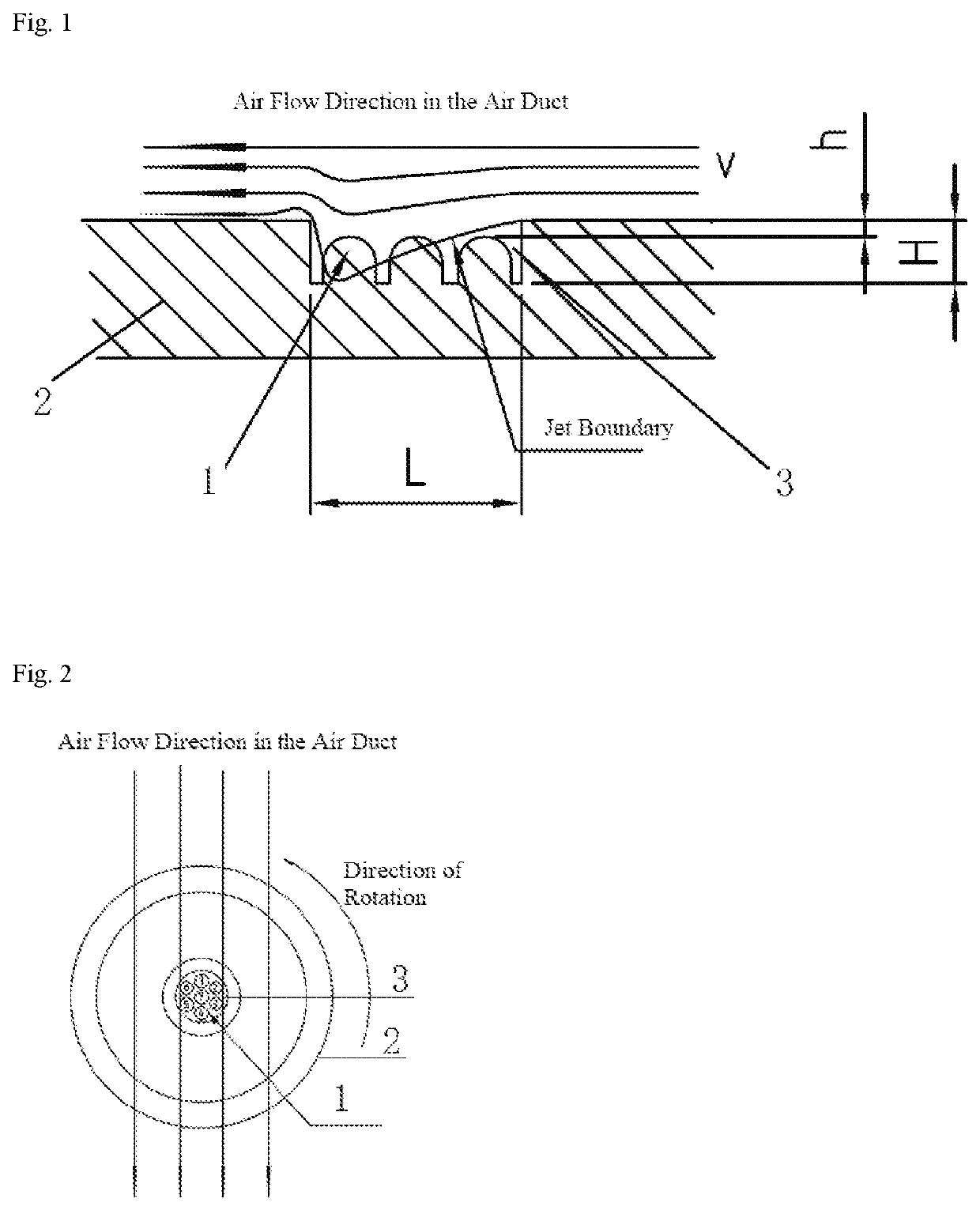
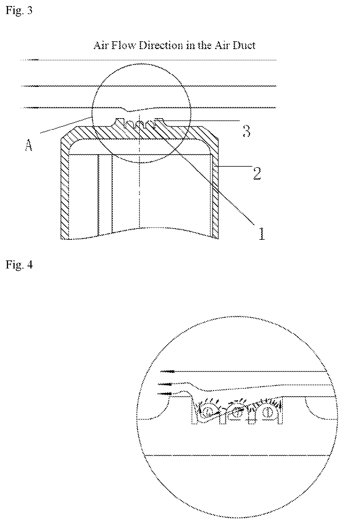
[0024]As shown in FIGS. 1-3, in a positive and negative wind pressure automatic cleaning method for an optical device, an optical device 1 positioned in a pit structure at the end of a rotor is placed in an air inlet duct. When a generator rotor rotates, a fan positioned on the generator rotor continuously sends airflow into the air inlet duct, and the rotation plane of the end of the rotor is parallel to the flow direction of the airflow;

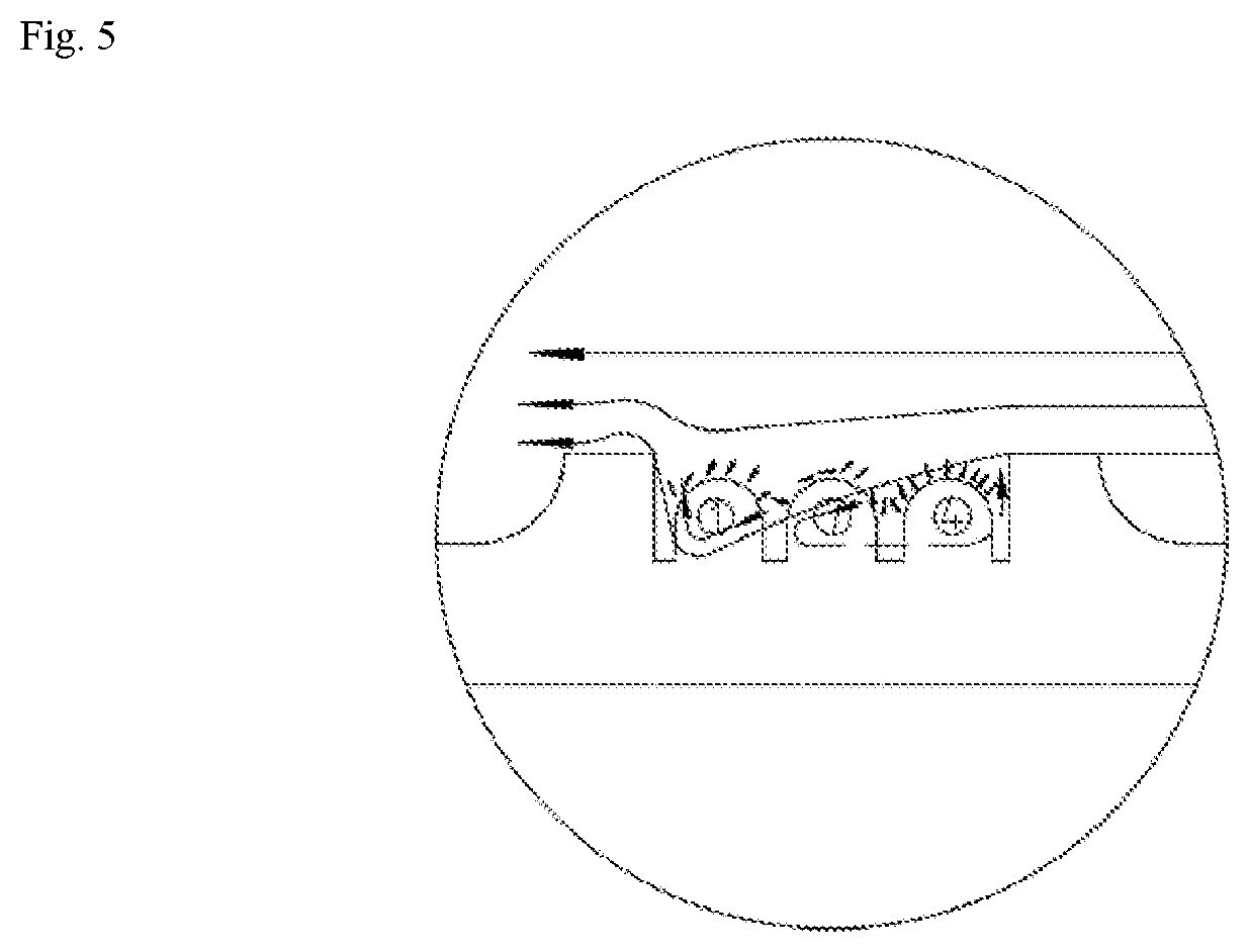
[0025]when the airflow passes through the edge of the pit structure at the end of the rotor, a jet effect is formed; due to the entrainment of the jet, the air which is still on the leeside is carried away by the entrainment; along with the addition of new air, the jet boundary diffuses outwards in the pit structure, forming one approximately triangular negative pressure area; the edge of the jet boundary diffuses to the top plane of the optical device; air in an area outside the jet boundary in the pit structure is carried away by the entrainment ...


PUM


Abstract

The invention discloses a positive and negative wind pressure automatic cleaning method for an optical device and belongs to the field of generator rotors. The invention discloses a positive and negative wind pressure automatic cleaning method for an optical device, which utilizes fast-flowing air in a parallel direction to form alternating positive and negative wind pressure on the surface of the optical device in a pit structure of a rotatory component to cause dust particle vibration to realize automatic cleaning. The invention realizes the automatic cleaning of the surface of the optical device and solves the problems that the rotor grounding detection precision and reliability are influenced due to dust accumulation.

Description

TECHNICAL FIELD[0001]The invention relates to the field of generator rotors, in particular to a positive and negative wind pressure automatic cleaning method for the optical device.BACKGROUND ART[0002]The optical device in the wireless rotary generator rotor grounding detection apparatus is easy to pollute in the long-term use process, and the detection precision is influenced. Because of different structures, at present, the cleaning method for a similar structure is mostly a manual cleaning method, namely periodically cleaning, or a plane transparent cover being installed on the surface to block dust and prevent dust accumulation on the surface of the optical device. But on one hand, the method increases the complexity of the structure and on the other hand the dust accumulation on the cover cannot be automatically cleaned such that when the time is long, the accuracy and the sensitivity of the detection of the optical device are still influenced. Only regular shutdowns and manual...

Claims


Application Information

Patent Timeline
Patent Type & Authority Applications(United States)
IPC IPC(8): B08B5/02B08B5/04G02B27/00
CPCB08B5/02G02B27/0006B08B5/04B08B13/00B08B5/00
Inventor FENG, JIANSHENG
Owner NANJING TURBINE POWER CONTROL CO LTD
Why Eureka
Try Eureka