
Electroluminescent Display Device Having Pixel Driving

a technology of pixel driving and display device, which is applied in the direction of instruments, static indicating devices, etc., can solve the problems of low-speed driving, flicker, and deterioration of luminance of first frame, and achieve the effect of reducing non-uniform luminan

Active Publication Date: 2021-06-17
LG DISPLAY CO LTD
View PDF0 Cites 3 Cited by
  • Summary
  • Abstract
  • Description
  • Claims
  • Application Information

AI Technical Summary

Benefits of technology

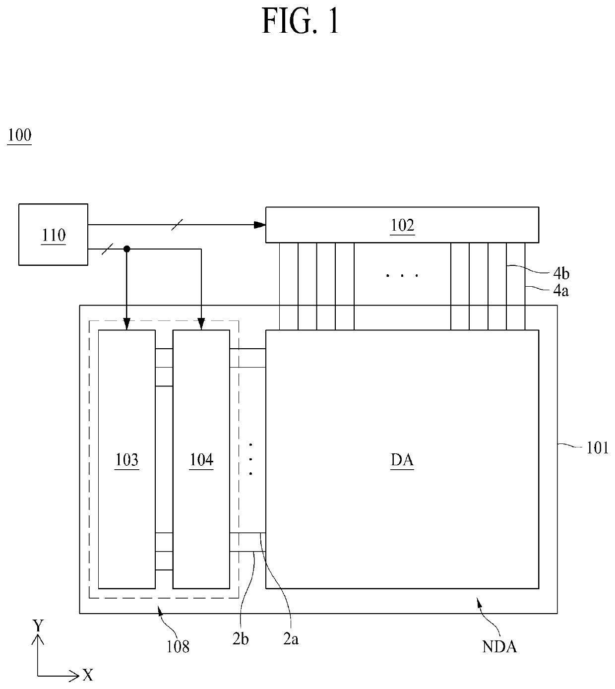
The present invention is an electroluminescent display device comprising a pixel driving circuit that can reduce non-uniform luminance and luminance deterioration during driving at a variable frequency. The pixel driving circuit includes a light emitting diode, a driving transistor including a gate, a drain and a source, a first switching circuit, a second switching circuit, a light emitting control circuit, a capacitor, and a high potential voltage. By applying a fixed voltage to the driving transistor and reducing leakage current, the device can improve its performance and stability.

Problems solved by technology

Also, if transistors included in a pixel driving circuit are embodied as P-type polysilicon transistors, a leakage current of a gate node of a driving transistor may occur during low-speed driving.
Since occurrence of the leakage current makes a light emitting diode difficult to maintain the same luminance for one frame and increases a data update period, flicker may be seen.
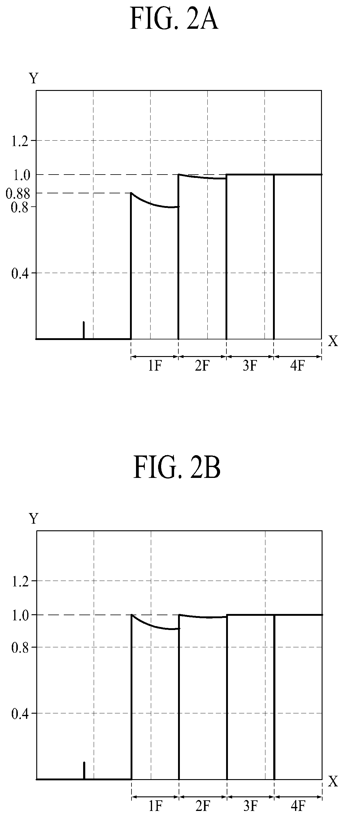
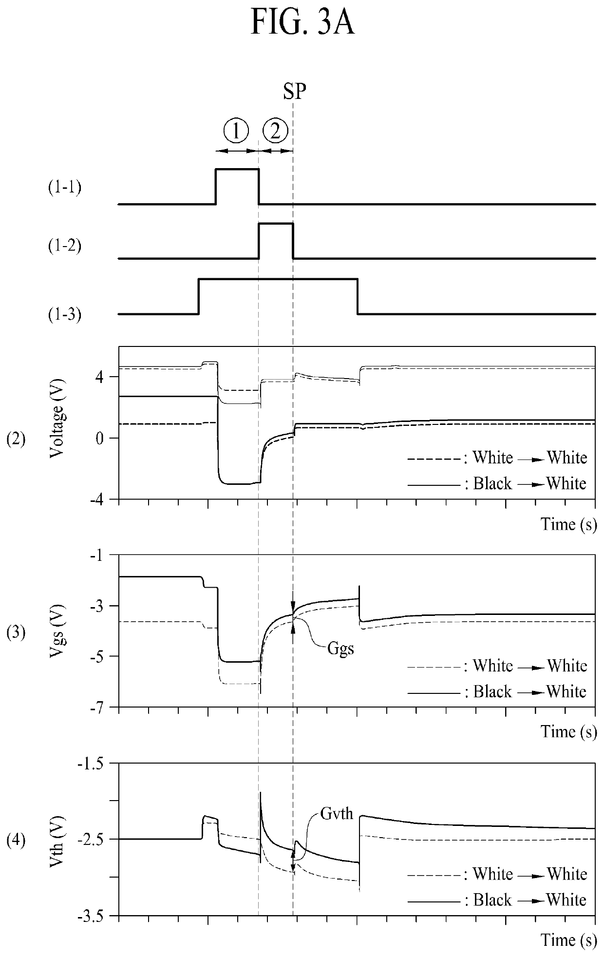
Also, luminance deterioration of a first frame is generated due to hysteresis of the driving transistor during switching from a black screen to a white screen.
Since luminance deterioration of the first frame causes high visibility during low-speed driving, quality of the electroluminescent display device may be deteriorated.

Method used


Image

  • Electroluminescent Display Device Having Pixel Driving
  • Electroluminescent Display Device Having Pixel Driving
  • Electroluminescent Display Device Having Pixel Driving

Examples


Embodiment Construction

[0027]Advantages and features of the present disclosure, and implementation methods thereof will be clarified through following embodiments described with reference to the accompanying drawings. The present disclosure may, however, be embodied in different forms and should not be construed as limited to the embodiments set forth herein. Rather, these embodiments are provided so that this disclosure will be thorough and complete, and will fully convey the scope of the present disclosure to those skilled in the art. Further, the present disclosure is only defined by scopes of claims.

[0028]A shape, a size, a ratio, an angle, and a number disclosed in the drawings for describing embodiments of the present disclosure are merely an example, and thus, the present disclosure is not limited to the illustrated details. Like reference numerals refer to like elements throughout the specification. In the following description, when the detailed description of the relevant known function or confi...


PUM


Abstract

An electroluminescent display device comprises subpixels each including a pixel driving circuit driven in accordance with an initialization period, a sampling period and a light emission period. The pixel driving circuit includes a light emitting diode, a driving transistor including a gate connected to a first node, a drain connected to a second node, and a source connected to a third node, a first switching circuit turned on for the initialization period, providing an initialization voltage to the first node and providing a fixed voltage to the third node, a second switching circuit turned on for the sampling period, applying a data voltage to the third node and providing the initialization voltage to an anode of the light emitting diode, and a light emitting control circuit controlled by an emission signal and turned on for the light emission period to provide a high potential voltage to the third node.

Description

CROSS-REFERENCE TO RELATED APPLICATIONS[0001]This application claims the benefit of Republic of Korea Patent Application No. 10-2019-0166499 filed on Dec. 13, 2019, which is hereby incorporated by reference in its entirety.BACKGROUNDTechnical Field[0002]The present disclosure relates to an electroluminescent display device comprising a pixel driving circuit, and more particularly, to an electroluminescent display device effective for variable frequency driving.Description of the Related Art[0003]With the advancement of the information technology, the market for a display device which is a connection medium between a user and information has grown. Various types of communications beyond information transfer based on text messages between users are actively ongoing. As the type of information changes, performance of a display device for displaying information has been developed. Therefore, various types of display devices such as an organic light emitting display device, a micro-LED d...

Claims


Application Information

Patent Timeline
IPC IPC(8): G09G3/32
CPCG09G3/32G09G2310/0275G09G2310/0267G09G3/3225G09G2320/0233G09G3/3233G09G2300/0819G09G2310/0262G09G2310/061G09G2310/067G09G2310/0245G09G2310/06G09G2330/021
Inventor KIM, JAESUNGKIM, KIWOOCHANG, SUNGWOOKKIM, HYUNGSOO
Owner LG DISPLAY CO LTD
Learn More