Light guide member having light mixing protrusion, flat light source device, and display device

a technology of light guide and protrusion, which is applied in the direction of planar/plate-like light guide, lighting and heating apparatus, instruments, etc., can solve the problems of color mixture insufficient, color unevenness, and increased demand for enlarging liquid crystal display, so as to reduce color unevenness

Inactive Publication Date: 2011-05-17
RESONAC HOLDINGS CORPORATION
View PDF18 Cites 49 Cited by
  • Summary
  • Abstract
  • Description
  • Claims
  • Application Information

AI Technical Summary

Benefits of technology

[0015]An object of the present invention is to provide a light guide member capable of reducing an unevenness of colors of a flat light source device in the case in which LED light sources of a plurality of colors such as RGB are used.
[0016]Another object of the present invention is to provide a light guide member capable of reducing a nonuniformity in luminance of a flat light source device caused by a higher luminance at the section directly over a light source.
[0017]Another object of the present invention is to provide a flat light source device in which an irregular luminescent color is reduced in the case in which LED light sources of a plurality of colors such as RGB are used.

Problems solved by technology

However, a demand of enlarging a liquid crystal display has been increased in recent years, and the edge light type has a limitation in the case in improving a luminance and a uniformity in the luminance.
However, in the case in which a color mixture is carried out by using LED light sources of a plurality of colors such as RGB, a color mixture is insufficient and unevenness of colors may be found.
In addition, there is a problem that a luminance of the section directly over the LED light sources becomes higher.
However, this method causes a thickness of a back light to be enlarged, and is not preferable for a flat panel display.
In addition, a luminance of the light guide plate at the position directly over the LED light sources becomes higher, and a nonuniformity in luminance cannot be canceled to a sufficient level.
Although the lens 31 can guide most lights emitted from the LED light source 5 in a horizontal direction, the shape of the lens is complicated.

Method used


Image

  • Light guide member having light mixing protrusion, flat light source device, and display device
  • Light guide member having light mixing protrusion, flat light source device, and display device
  • Light guide member having light mixing protrusion, flat light source device, and display device

Examples


example 1

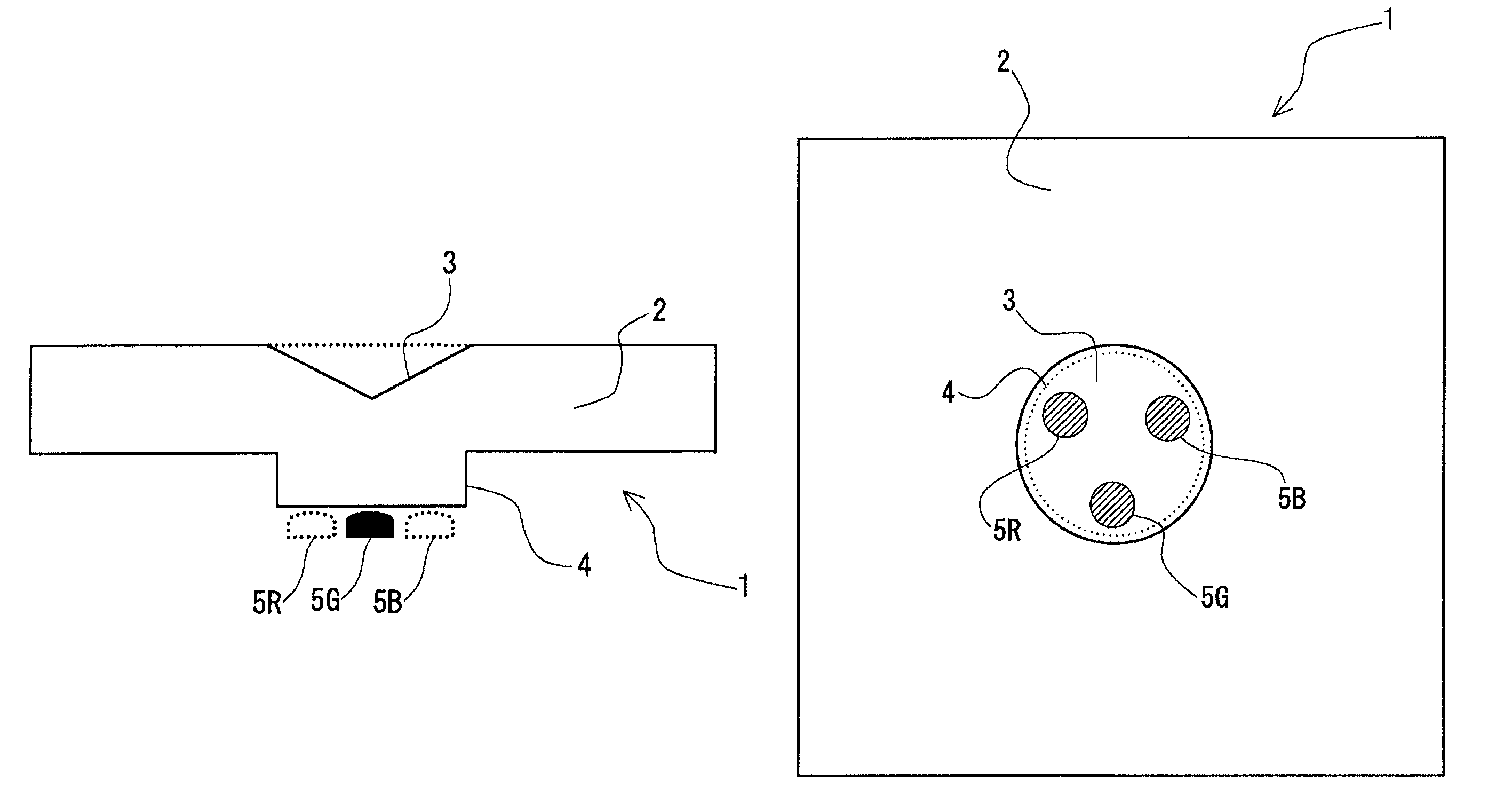
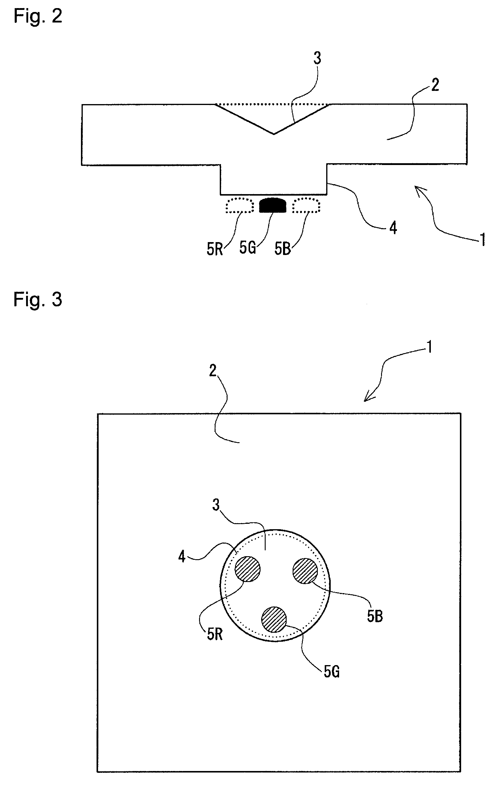
[0109]There was fabricated a light guide member, as shown in FIG. 4, provided with a square light guide portion with a side of 50 mm and with a thickness of 12 mm, a cylindrical protrusion with a diameter of 6 mm and with a height of 6 mm, and a conical depression with a diameter of 14 mm and with an inclination angle of 60 degrees by cutting an acrylic plate with a thickness of 18 mm (product name: SUMIPEX, manufactured by Sumitomo Chemical Co., Ltd.) by using a milling machine.

[0110]There was then fabricated an LED package in which a 0.5 W class red LED chip and 1 W class blue and green LED chips were mounted / disposed at a 1.5 mm pitch at vertex positions of an almost equilateral triangle in a package in which a copper wiring pattern capable of mounting an LED on a square substrate with a side of 13 mm was formed and in which a reflector was formed with a bottom face diameter of 6 mm, with a top face diameter of 6 mm, and with a height of 0.5 mm.

[0111]A material of the reflector w...

example 2

[0113]There was fabricated a light guide member with a size equivalent to that of Example 1, provided with a cylindrical counter boring hole with a diameter of 4 mm on the bottom face of the protrusion, by metal molding using the epoxy resin (product name: NLD-SL-1101 manufactured by SANYU REC CO. LTD.).

[0114]Moreover, an LED package equivalent to that of Example 1 was fabricated except that there was no reflector and no epoxy resin sealing.

[0115]The above epoxy resin was filled into the cylindrical counter boring hole of the protrusion of the light guide member, and the light guide member was bonded to the LED package in such a manner that each of LED chips of red, green, and blue is disposed in the cylindrical counter boring hole. The heat setting at 100° C. for two hours and then at 130° C. for three hours was carried out to integrate the light guide member with the LED package.

example 3

[0116]An LED package with a light guide member was fabricated similarly to Example 1 except that a white reflecting layer was formed on the side face of the protrusion of Example 1. The white reflecting layer was formed by coating a pigment paint (product name: White type number 01 of Acrylic lacquer spray manufactured by Nippon Paint Home Products Co., Ltd.) with a thickness of approximately 100 mm.


PUM


Abstract

A light guide member capable of reducing an unevenness of luminescent color and further a nonuniformity in luminance when obtaining a white color by a color mixture using a plurality of light sources. Also disclosed are a flat light source device and a display device. A protrusion (4) of a cylindrical shape is formed upward a plurality color of LED light sources 5R, 5G, 5B, e.g., RGB color at a backside face of a light guide member (1), and a conical depression (3) is disposed at the position directly over the protrusion. Lights of each color from LED light sources 5R, 5G, 5B are mixed at the protrusion (4), thereafter reflect at the depression (3) and propagate in a horizontal direction at a light guide portion (2).

Description

CROSS REFERENCES OF RELATED APPLICATION[0001]This application is an application filed under 35 U.S.C. §111(a) claiming benefit pursuant to 35 U.S.C. §119(e)(1) of the filing date of Provisional Application 60 / 755,791 filed on Jan. 4, 2006 pursuant to 35 U.S.C. §111(b).TECHNICAL FIELD[0002]The present invention relates to a light guide member for a flat light source device, a flat light source device using the light guide member, and a display device provided with the flat light source device that are used as a back light for a liquid crystal display for instance.BACKGROUND OF THE INVENTION[0003]In recent years, a light emission efficiency of a light-emitting diode device has been extremely improved, and an application of the luminous diode device to an illumination is being progressed. In particular, in the case in which there is used a light emitting diode device as a back light for a liquid crystal display, a satisfactory gamut of reproducible colors and a high speed response can ...

Claims


Application Information

Patent Timeline
Patent Type & Authority Patents(United States)
IPC IPC(8): F21V9/00
CPCG02B6/0018G02F1/133609G02F1/133603G02B6/0068
Inventor NAIJO, SHUICHIGOMI, SHUJIWATANABE, TAKEO
Owner RESONAC HOLDINGS CORPORATION
Why Eureka
Try Eureka