Optical fiber scanning probe and endoscope having the same

a fiber scanning probe and endoscope technology, applied in the field of optical fiber scanning probes and endoscopes, can solve the problems of complicated architecture, unfavorable miniaturization of fiber scanning probes, and medical risks

Active Publication Date: 2021-06-24
IND TECH RES INST
View PDF0 Cites 0 Cited by
  • Summary
  • Abstract
  • Description
  • Claims
  • Application Information

AI Technical Summary

Benefits of technology

The conventional OCT system has limitations in achieving two-dimensional CT imaging as it requires a scanning mechanism at the sample arm, which can pose medical risks during endoscopy or cardiac catheter treatments due to electric shock or electromagnetic interference. Additionally, the movement of fiber can result in changes in inclination of the output end, which requires adjustment of the optical path with the optical lens set. This makes the fiber scanning probe architecture complicated and not conducive to miniaturization.

Problems solved by technology

This poses electric shock or electromagnetic interference to human tissues, which leads to medical risks during endoscopy or cardiac catheter treatments.
This will require the adjustment of the optical path with the optical lens set, so the architecture is complicated and not conducive to miniaturize the fiber scanning probe.

Method used


Image

  • Optical fiber scanning probe and endoscope having the same
  • Optical fiber scanning probe and endoscope having the same
  • Optical fiber scanning probe and endoscope having the same

Examples


Embodiment Construction

[0019]In the following detailed description, for purposes of explanation, numerous specific details are set forth in order to provide a thorough understanding of the disclosed embodiments. It will be apparent, however, that one or more embodiments may be practiced without these specific details. In other instances, well-known structures and devices are schematically shown in order to simplify the drawings.

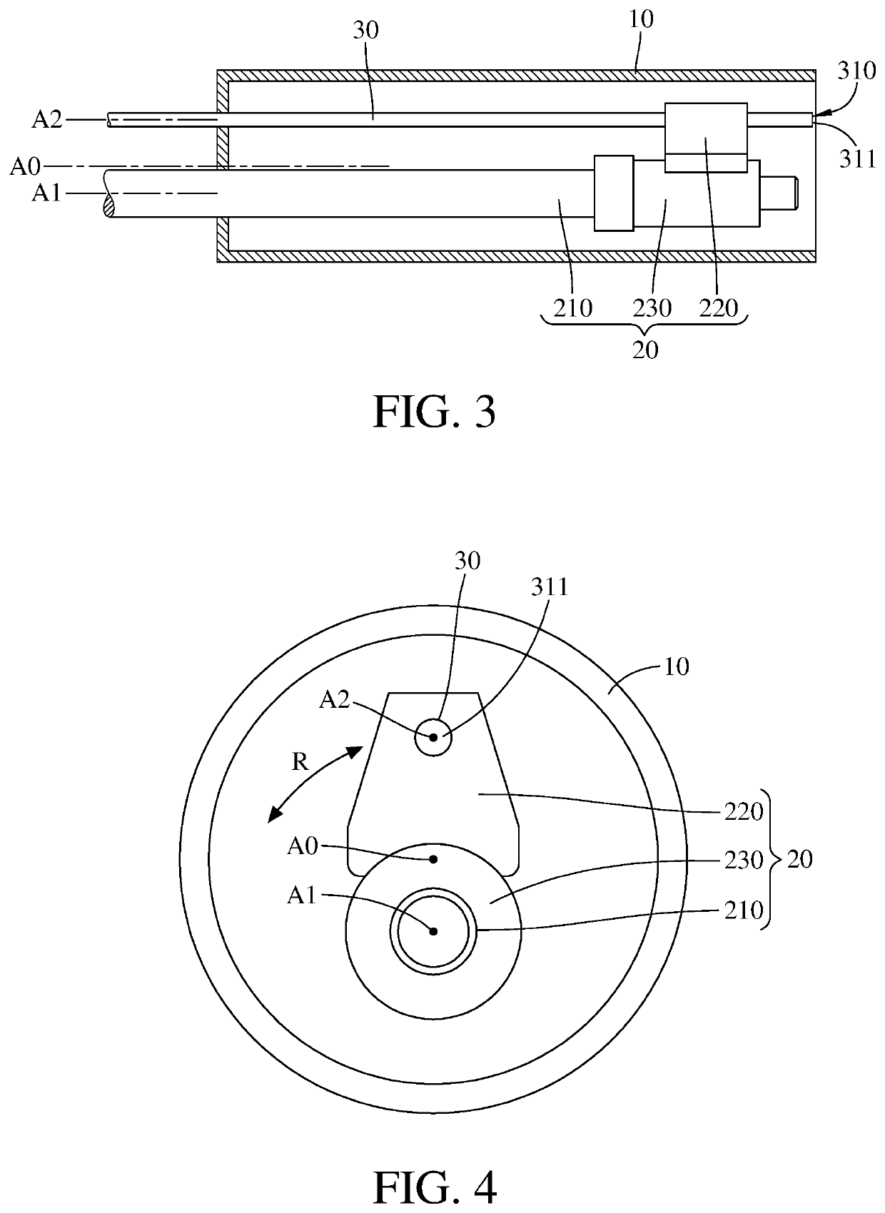
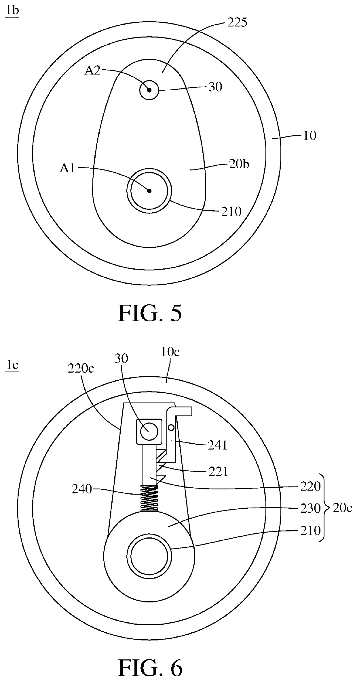
[0020]According to the present disclosure, the descriptions “element A is eccentric relative to element B” and “element A is eccentrically disposed on / in element B” are directed to that the center of element A is spaced apart from the center of element B. In some cases, it is more specifically directed to that the central axis of element A is spaced apart from the central axis of element B; that is, element A is not coaxial with element B.

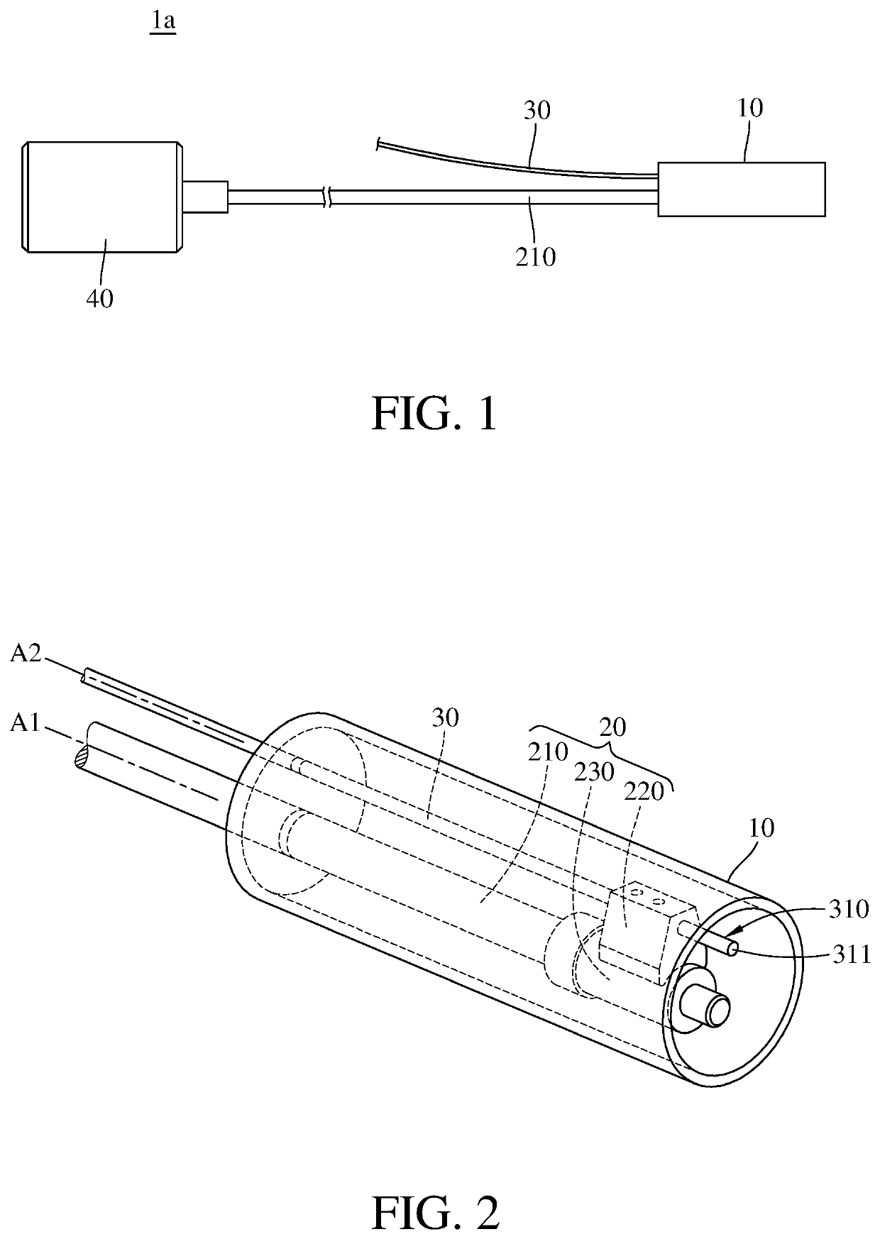
[0021]According to one embodiment of the disclosure, an optical fiber scanning probe includes a rotor and at least one optical fiber. Please refe...


PUM

PropertyMeasurementUnit
distanceaaaaaaaaaa
distancesaaaaaaaaaa
sizeaaaaaaaaaa

Abstract

An optical fiber scanning probe includes a rotor and at least one optical fiber. The rotor includes a torque rope rotatable about its central axis. The optical fiber is disposed on the rotor and eccentric relative to the torque rope. A central axis of the optical fiber is substantially parallel to the central axis of the torque rope. When the torque rope rotates about its central axis, the rotor brings a free end of the optical fiber to scan along an arc path.

Description

CROSS-REFERENCE TO RELATED APPLICATIONS[0001]This non-provisional application claims priority under 35 U.S.C. § 119(a) on Patent Application No(s). U.S. 62 / 953,010 filed in U.S. on Dec. 232019, and Patent Application No(s). 109117181 filed in Taiwan R.O.C. on May 22, 2020, the entire contents of which are hereby incorporated by reference.BACKGROUND1. Technical Field[0002]This present disclosure relates to an optical fiber scanning probe and an endoscope including the optical fiber scanning probe.2. Related Art[0003]Optical coherence tomography (OCT), which is a rapidly developing endovascular imaging technology in recent years, reconstructs two-dimensional or three-dimensional structure of biological tissues by optical scanning. OCT features non-free energy field source, high resolution, high speed scanning and imaging. At present, the most common application of OCT is a fiber scanning probe disposed on the distal end of the endoscope or cardiac catheter, and biological tissues from...

Claims


Application Information

Patent Timeline
Patent Type & Authority Applications(United States)
IPC IPC(8): A61B1/00G02B26/10H04N5/225A61B5/00A61B1/05
CPCA61B1/00172G02B26/103A61B1/00165H04N5/2252H04N2005/2255A61B5/0066A61B1/05A61B5/0084A61B1/00032A61B1/3137A61B1/07A61B1/00117A61B5/0073A61B1/00097H04N23/555H04N23/51
Inventor HUANG, CHUN-CHIEHLEE, YUAN CHINCHANG, CHI SHENCHIANG, HUNG CHIH
Owner IND TECH RES INST
Why Eureka
Try Eureka