
Device for the two-dimensionally scanning beam deflection of a light beam

a two-dimensional scanning and light beam technology, applied in measurement devices, electromagnetic wave reradiation, instruments, etc., can solve the problems of high resolution, difficult to combine large mirror diameters with sufficiently high scanning speed, and limited achievable deflection angles, so as to achieve sufficient speed and high resolution. the effect of two-dimensional scanning process

Pending Publication Date: 2021-06-24
CARL ZEISS SMT GMBH
View PDF0 Cites 4 Cited by
  • Summary
  • Abstract
  • Description
  • Claims
  • Application Information

AI Technical Summary

Benefits of technology

The invention is a device that uses prisms to scan light in two dimensions. By arranging the prisms in a way that causes the light to move back and forth, the prisms can perform a scan without needing to move any other optical components. This makes the device more robust and compact, as it doesn't need to be much bigger than the light beam. The device can also use different light beams with different wavelengths or tuning ranges in parallel, which allows for faster and more efficient scanning. The prisms can be designed to be insensitive to the wavelength of the light, which ensures the device works well even with different light sources or frequency combs. The device may also include a polarizer to adjust the polarization of the light beam to maximize the efficiency of the first component.

Problems solved by technology

However, carrying out a two-dimensional scanning process with a sufficiently high speed and high resolution, for instance when scanning objects such as vehicles, represents a great challenge in practice.
In this case, for example, when using MEMS-based scanning mirrors, it proves problematic to combine large mirror diameters with a sufficiently high scanning speed, the achievable deflection angles also being limited because of the solid-state articulations used.
Further approaches based on mechanical scanning mirrors or based on a combination of rotation and dispersion scanners have, inter alia, the disadvantage of a relatively complex structure and a significant installation space requirement.

Method used


Image

  • Device for the two-dimensionally scanning beam deflection of a light beam
  • Device for the two-dimensionally scanning beam deflection of a light beam
  • Device for the two-dimensionally scanning beam deflection of a light beam

Examples


Embodiment Construction

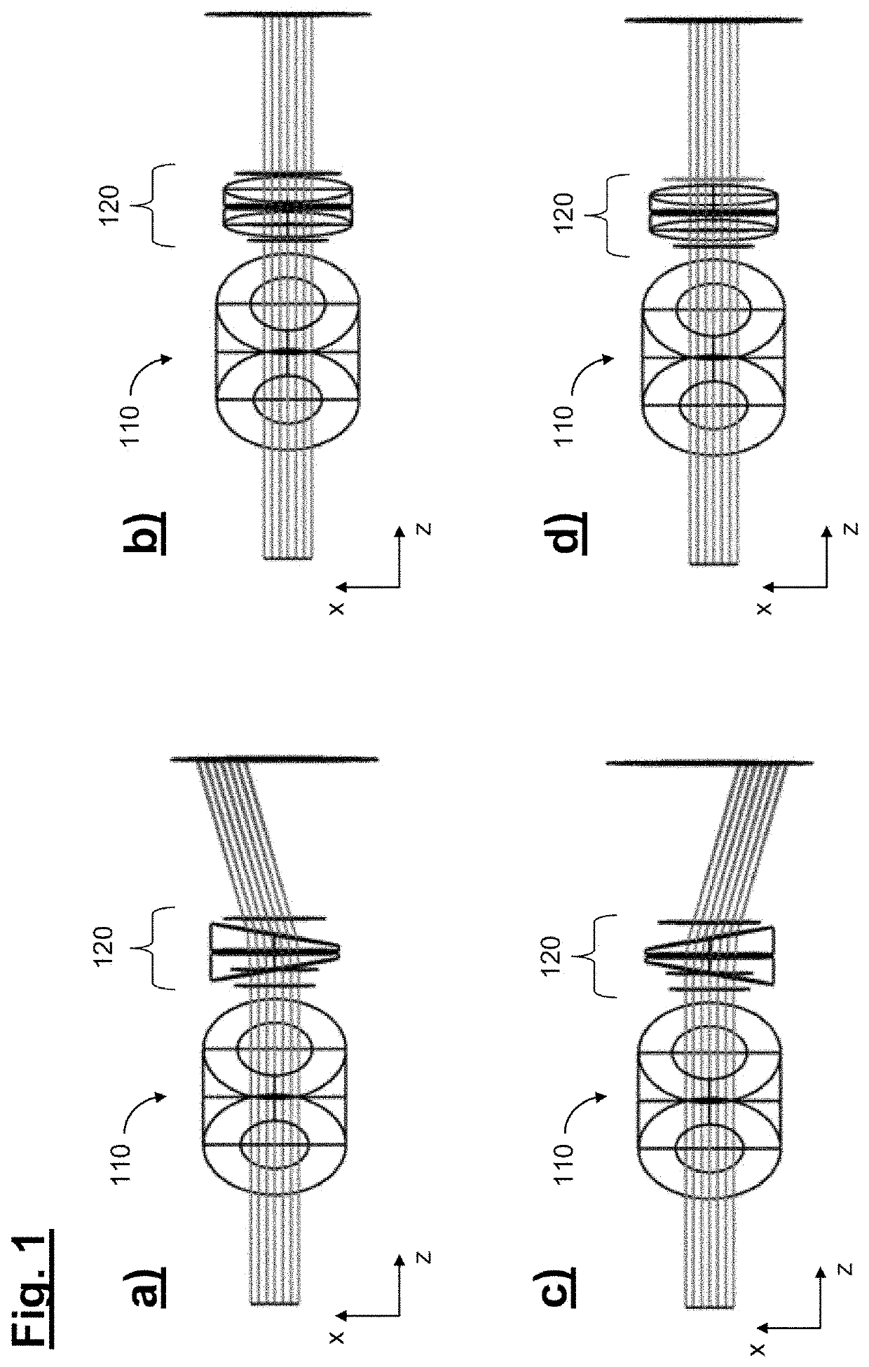
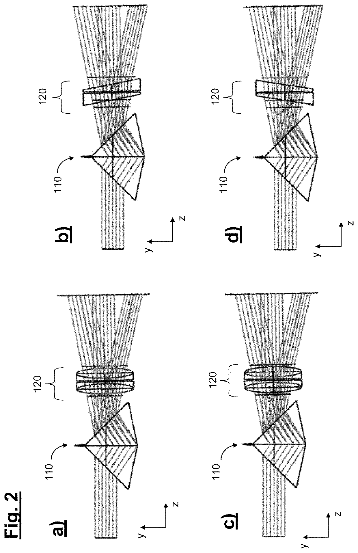
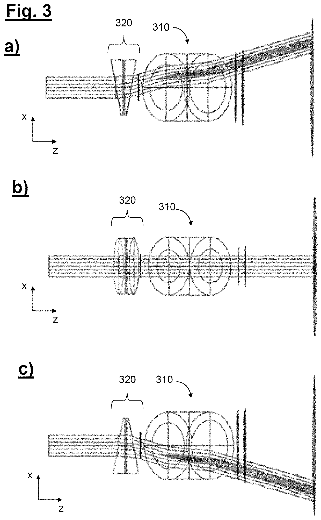
[0036]The basic possible structure and the functionality of a device according to the invention for two-dimensionally scanning beam deflection will be described below with the aid of different embodiments with reference to the schematic drawings of FIG. 1-4.

[0037]The device according to the invention has at least one light source, which is spectrally tunable (i.e. it is variable in terms of the wavelength of the emitted light), for emitting at least one light beam with a time-varying wavelength. In further embodiments, a plurality of light beams with a different wavelength or a different tuning range may also be provided for the purpose of time-parallelization of the scanning process, which may in turn be carried out by using a plurality of light sources or alternatively also by generating a frequency comb.

[0038]A common feature of the embodiments described below is that—for the two-dimensionally scanning beam deflection of at least one light beam with a time-varying wavelength prod...


PUM

PropertyMeasurementUnit
rotation angleaaaaaaaaaa

Abstract

A device for two-dimensionally scanning beam deflection of a light beam has spectrally tunable light source that emits a light beam having a time-varying wavelength. The device further comprises a first optical component that produces a first beam deflection. The first beam deflection causes the light beam to be deflected wavelength-dependently in a first direction. A second optical component produces a second beam deflection which causes the light beam to be deflected in a second direction different to the first direction. The second optical component comprises a prism pair comprising two prisms that are rotatably arranged successively in a beam path of the light beam. The two prisms are configured to perform continuous counter-rotational movements.

Description

CROSS-REFERENCE TO RELATED APPLICATIONS[0001]The present application claims benefit of German patent application 10 2019 135 759.4 filed on Dec. 23, 2019. The entire disclosure of this earlier patent application is incorporated herein by reference.BACKGROUND OF THE INVENTIONField of the Invention[0002]The invention relates to a device for the two-dimensionally scanning beam deflection of a light beam. The device may, in particular, be used for scanning beam deflection during the determination of distances of both moving and stationary objects and for determination of the topography or shape of one or more spatially extended three-dimensional objects.Prior Art[0003]For the optical distance measurement of objects, inter alia a measurement principle also referred to as LIDAR is known, in which an optical signal time-varied continuously in its frequency is radiated towards the object in question and is evaluated after reflection has taken place back from the object.[0004]FIG. 5a shows, ...

Claims


Application Information

Patent Timeline
Patent Type & Authority Applications(United States)
IPC IPC(8): G02B26/10G02B26/08G02B5/04G01S7/481G01S17/08G01S7/48
CPCG02B26/108G02B26/101G02B26/0891G01S7/4808G02B26/106G01S7/4817G01S17/08G02B5/04G01S17/34G01S7/4812
Inventor HÖLLER, FRANKWINKLER, KERSTINKOCH, FELIX
Owner CARL ZEISS SMT GMBH
Learn More