
An underground soil sensors system

Inactive Publication Date: 2021-07-01
CROPX TECH
View PDF0 Cites 3 Cited by
  • Summary
  • Abstract
  • Description
  • Claims
  • Application Information

AI Technical Summary

Benefits of technology

The patent describes a sensor that can measure the water content in soil. It consists of two electrodes that are positioned between which the water content is measured. The sensor is attached to a support that takes up less than 10% of the space where the water content is measured. This allows for accurate readings of soil water content without interfering with the measurements. The invention can be used in agricultural or forest soil monitoring, for example.

Problems solved by technology

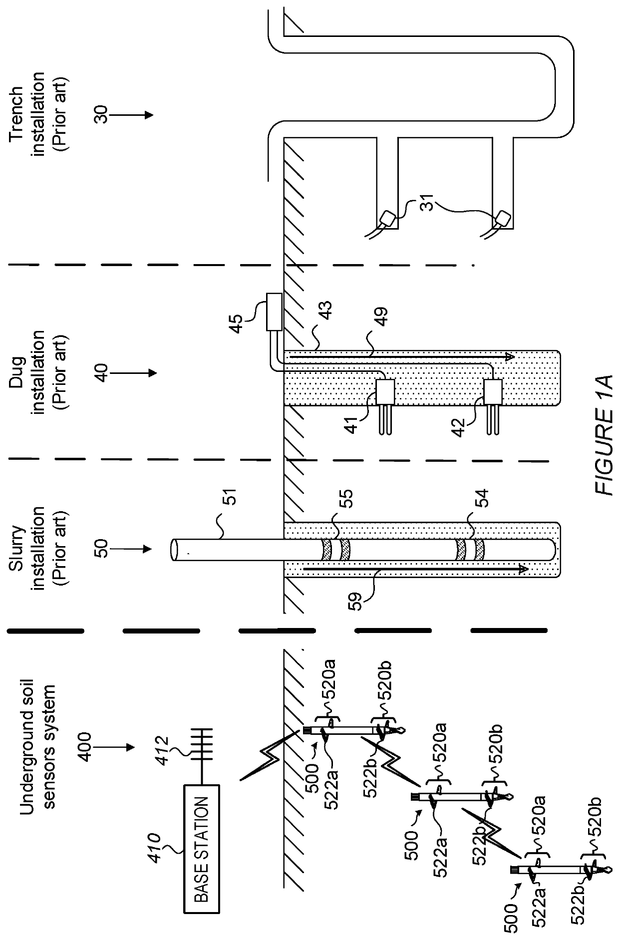
Typically, current VWC sensors can significantly disturb a target soil during an installation and / or can require pre-drilling procedures in order to be installed.
Unmatched pre-drilling and VWC sensor's dimensions can result in a poor contact between the VWC sensor and the soil.
The poor contact between the soil sensor and the soil and / or disturbed soil can introduce measurement errors.
For example, a gap can be generated between the VWC sensor and the soil, in which vertical water flow and / or accommodation can occur, thereby affecting the VWC measurement of the target soil.
Moreover, the pre-drilling requirement can increase the installation costs.
Wired connections between the soil sensors and / or between the soil sensors and the base station can be damaged during a working of a target soil.
Moreover, wired connections can increase installation costs.
Wireless connections between the soil sensors and the base station can be restricted by a reduced transmitting power of the soil sensors due to soil attenuation of the RF signals.
Accordingly, a depth at which the soil sensors can be installed can be limited.

Method used


Image

  • An underground soil sensors system
  • An underground soil sensors system
  • An underground soil sensors system

Examples


Embodiment Construction

[0032]Effective agriculture can depend on obtaining accurate, continuous, in-field soil measurements, for example soil moisture measurements, including soil measurements at different sub-surface depths. A target soil can be non-uniform and therefore continuous measurements can be required to be measured at multiple locations in a field to, for example, best inform agricultural actions. For example, different parts of the field can require different amounts of irrigation, which can require continuous soil-moisture monitoring at different specific locations in the field. Current soil sensor devices can invariably provide biased measurements of sub-soil due to the disturbance of the soil, caused by, for example, their installation. Current scientific installation procedures that can provide, for example, unbiased measurements, can be complex and / or impractical in a working agricultural field. Current soil sensor devices typically do not provide practical, accurate, continuous and / or in...


PUM


Abstract

An underground soil sensors system is disclosed. The underground soil sensors system can include a base station having at least one antenna. The underground soil sensors system can include at least one set of soil sensors, where each soil sensor in the at least one set can be positioned at a predetermined vertical distance below a surface of a target soil. Each soil sensor in the at least one set can transmit signals to an adjacent soil sensor positioned thereabove in that set and to receive signals from an adjacent soil sensor positioned therebelow in that set. A topmost soil sensor in the at least one set can transmit signals to the at least one antenna of the base station.

Description

BACKGROUND OF THE INVENTION1. Technical Field[0001]The present invention relates to the field of soil sensors, and more particularly, to an underground soil sensors system.2. Discussion of Related Art[0002]Current volumetric water content (VWC) profile sensors can include a pole and / or circular radiofrequency (RF) electrodes wrapped around the pole. Typically, current VWC sensors can significantly disturb a target soil during an installation and / or can require pre-drilling procedures in order to be installed. Unmatched pre-drilling and VWC sensor's dimensions can result in a poor contact between the VWC sensor and the soil. The poor contact between the soil sensor and the soil and / or disturbed soil can introduce measurement errors. For example, a gap can be generated between the VWC sensor and the soil, in which vertical water flow and / or accommodation can occur, thereby affecting the VWC measurement of the target soil. Moreover, the pre-drilling requirement can increase the install...

Claims


Application Information

Patent Timeline
IPC IPC(8): A01G25/16G01N33/24G08C17/02
CPCA01G25/167G01N2033/245G08C17/02G01N33/246G08C17/00H04W84/18H04Q2209/40H04Q9/00G01N33/245
Inventor HARAN, YOSSI
Owner CROPX TECH
Learn More