Electrocardiograph lead wire

a technology of electrocardiograph and lead wire, which is applied in the field of electrocardiograph lead wire, can solve the problems of poor contact, affecting accuracy and stability, inconvenience to the operation of medical staff, etc., and achieves the effect of stable and reliable signal transmission

Pending Publication Date: 2021-07-01
NINGBO XINWELL MEDICAL TECH CO LTD
View PDF2 Cites 0 Cited by
  • Summary
  • Abstract
  • Description
  • Claims
  • Application Information

AI Technical Summary

Benefits of technology

[0025]According to the ECG lead wire of the aforesaid embodiments, the left electrode and the right electrode are arranged in a stacked manner to form an accommodation hole for the electrode contact to pass through, and at least one of the left electrode and the right electrode is made of an elastic material and / or driven by an elastic member, so that the left electrode and the right electrode can move relative to each other under the action of external force to widen the accommodation hole and can move relative to each other under an elastic force to narrow the accommodation hole. Since the size of the accommodation hole can be changed, the electrode holder can be adapted to electrode contacts of various sizes available on the market to make the electrode contacts be fixedly connected, thereby ensuring stable and reliable signal transmission.

Problems solved by technology

However, since the size of electrode contacts produced by different manufacturers is not uniform, it is easy to cause the problem of poor contact during an electrode contact produced by a certain manufacturer matching an electrode holder produced by other manufacturer.
Consequently, it results in unstable or interrupted signal transmission, affecting the accuracy and stability of data of ECG monitoring and detection and also inconvenience to the operation of medical staff.

Method used


Image

  • Electrocardiograph lead wire
  • Electrocardiograph lead wire
  • Electrocardiograph lead wire

Examples


embodiment 1

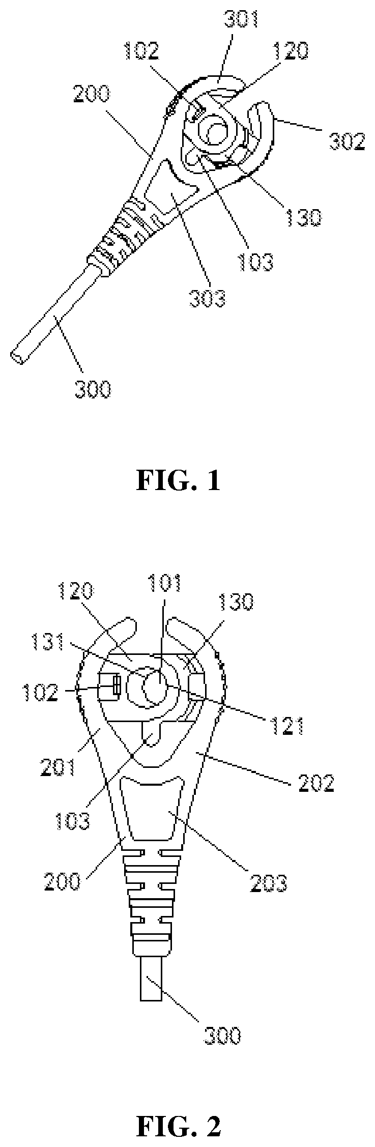
[0041]An ECG lead wire provided in this embodiment is used to connect a signal acquisition part and transmit electrical signals collected by the signal acquisition part to a host device.

[0042]The ECG lead wire includes an electrode holder 100, a sleeve body 200 and a connecting line 300, please refer to FIGS. 1-3. The electrode holder 100 is used to directly contact an electrode contact and transfer the electrical signals collected by the electrode contact to the connecting line 300, and then to the host device for processing via the connecting line 300.

[0043]The electrode holder 100 includes a connecting member 110, a left electrode 120, and a right electrode 130. At least one of the left electrode 120 and the right electrode 130 is coupled to the connecting member 110 which can be used to connect with the connecting member 300 for transmission of electrical signals. The left electrode 120 and the right electrode 130 are stacked and enclose an accommodation hole 101 for the electro...

embodiment 2

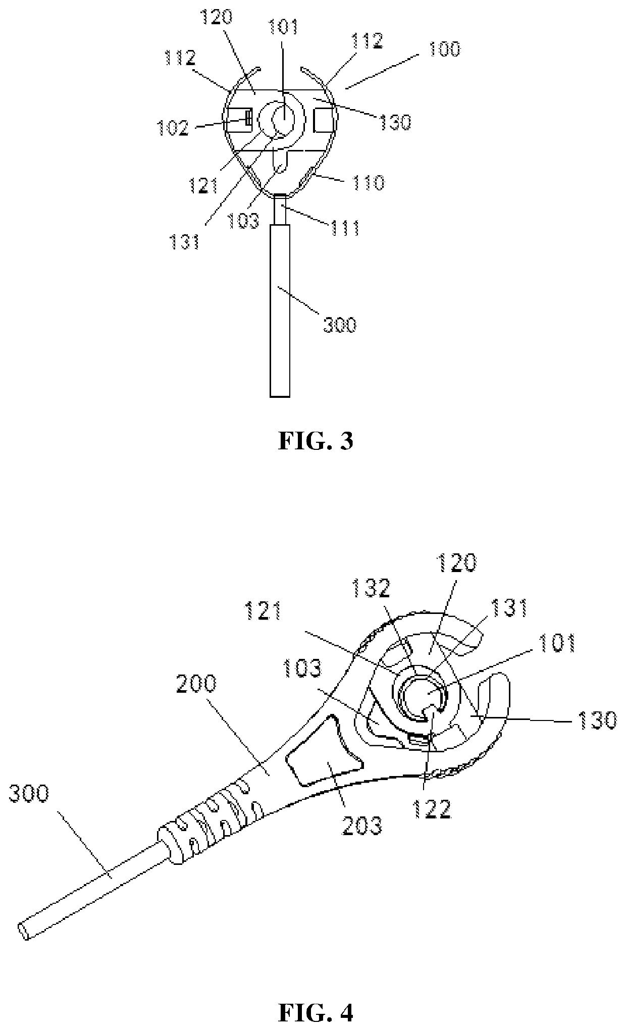
[0064]Provided in Embodiment 2 is another ECG lead wire.

[0065]Please referring to FIGS. 4-5, the difference between the ECG lead wire shown in this embodiment and Embodiment 1 is that the left electrode 120 and the right electrode 130 each are in a sheet structure herein. The left electrode 120 has a first through hole 121, and the right electrode 130 has a second through hole 131. The second through hole 131 is arranged in the first through hole 121. The edge of the second through hole 131 is protruded toward the first through hole 121 to form a limiting portion 132. The limiting portion 132 is passed through the first through hole 121 to limit the closest position where the left electrode 120 and the right electrode 130 approach each other and the farthest position they are away from each other.

[0066]The limiting portion 132 may form a ring structure (closed or unclosed) and be arranged in the first through hole 121. Therefore, the limiting portion 132 has both the functions of th...

embodiment 3

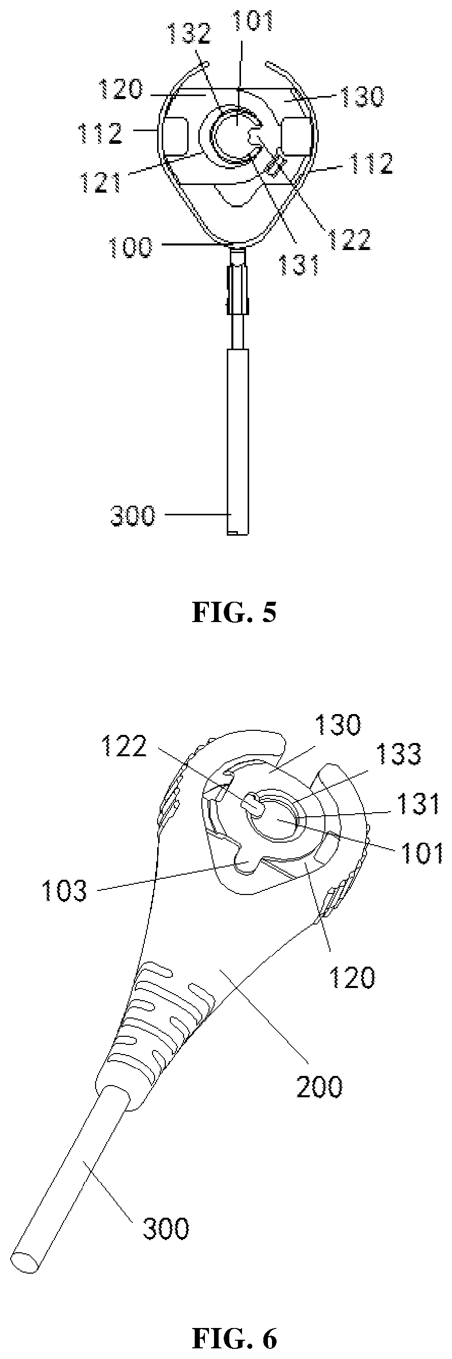
[0069]Provided in Embodiment 3 is still another ECG lead wire.

[0070]Please refer to FIGS. 6-8. The difference between the ECG lead wire shown in this embodiment and Embodiment 2 is that the wall of the second through hole 131 can be configured in an arc-shaped transition 133 having a large outer diameter and a small inner diameter. In this respect, the electrode contact is handily guided to be inserted into the second through hole 131, so that the connection therebetween can be realized by an operator with his / her hand without looking at them.

[0071]In addition, the anti-misplacing baffle 103 in the ECG lead wire provided in this embodiment is in a shape similar to that in Embodiment 1.


PUM


Abstract

Disclosed is an electrocardiograph (ECG) lead wire. The left electrode (120) and the right electrode (130) of the ECG lead wire are stacked and enclose an accommodation hole (101) for an electrode contact to pass through. At least one of the left electrode (120) and the right electrode (130) is made of an elastic material and/or is driven by an elastic member, so that the left electrode (120) and the right electrode (130) can move relative to each other under the action of an external force to widen the accommodation hole (101), and can move relative to each other under an elastic action force to narrow the accommodation hole (101). Since the size of the accommodation hole (101) can change, the electrode holder can be adapted to electrode contacts of various sizes on the market and makes same be firmly connected, thereby ensuring the stability and reliability of signal transmission.

Description

TECHNICAL FIELD[0001]The present disclosure relates to electrocardiographic (ECG) devices, in particular to the structure of an ECG lead wire.BACKGROUND OF THE INVENTION[0002]ECG monitors and ECG machines have become increasingly important medical monitoring and detecting equipment with the development of science and technology and the continuous improvement of medical standards. Generally speaking, host device, signal transmission features and signal acquisition features are the three important parts of ECG monitoring and detection. The signal acquisition features are usually connected by electrode holders with the signal transmission features. The electrode holders available on the market can be divided into several ways including clamp type, buckle type and banana-plug type. However, since the size of electrode contacts produced by different manufacturers is not uniform, it is easy to cause the problem of poor contact during an electrode contact produced by a certain manufacturer...

Claims


Application Information

Patent Timeline
Patent Type & Authority Applications(United States)
IPC IPC(8): A61B5/282A61B5/30A61B5/308
CPCA61B5/282A61B2562/225A61B5/303A61B2562/227A61B5/273
Inventor ZHOU, YUBOYU, JIEWEI
Owner NINGBO XINWELL MEDICAL TECH CO LTD
Why Eureka
Try Eureka