
Medical device, control method, and computer-readable storage medium

a control method and medical device technology, applied in medical science, surgery, surgical instruments for heating, etc., can solve problems such as deterioration of treatment performance of biological tissue, and achieve the effect of reducing an output valu

Pending Publication Date: 2021-07-01
OLYMPUS CORP
View PDF0 Cites 0 Cited by
  • Summary
  • Abstract
  • Description
  • Claims
  • Application Information

AI Technical Summary

Benefits of technology

This patent describes a control program for a medical device that can reduce the output of a high-frequency signal when there is a fluctuation in voltage or mechanical load on the device. This program can help to ensure the safety and effectiveness of the medical device during use.

Problems solved by technology

Here, in a case where an electroconductive member such as a metal forceps comes into contact with the end effector while treating the biological tissue, the high-frequency energy that should be used for the treatment of the biological tissue may be discharged, and treatment performance of the biological tissue may be deteriorated.

Method used


Image

  • Medical device, control method, and computer-readable storage medium
  • Medical device, control method, and computer-readable storage medium
  • Medical device, control method, and computer-readable storage medium

Examples


first embodiment

[0017]Schematic Configuration of Medical System

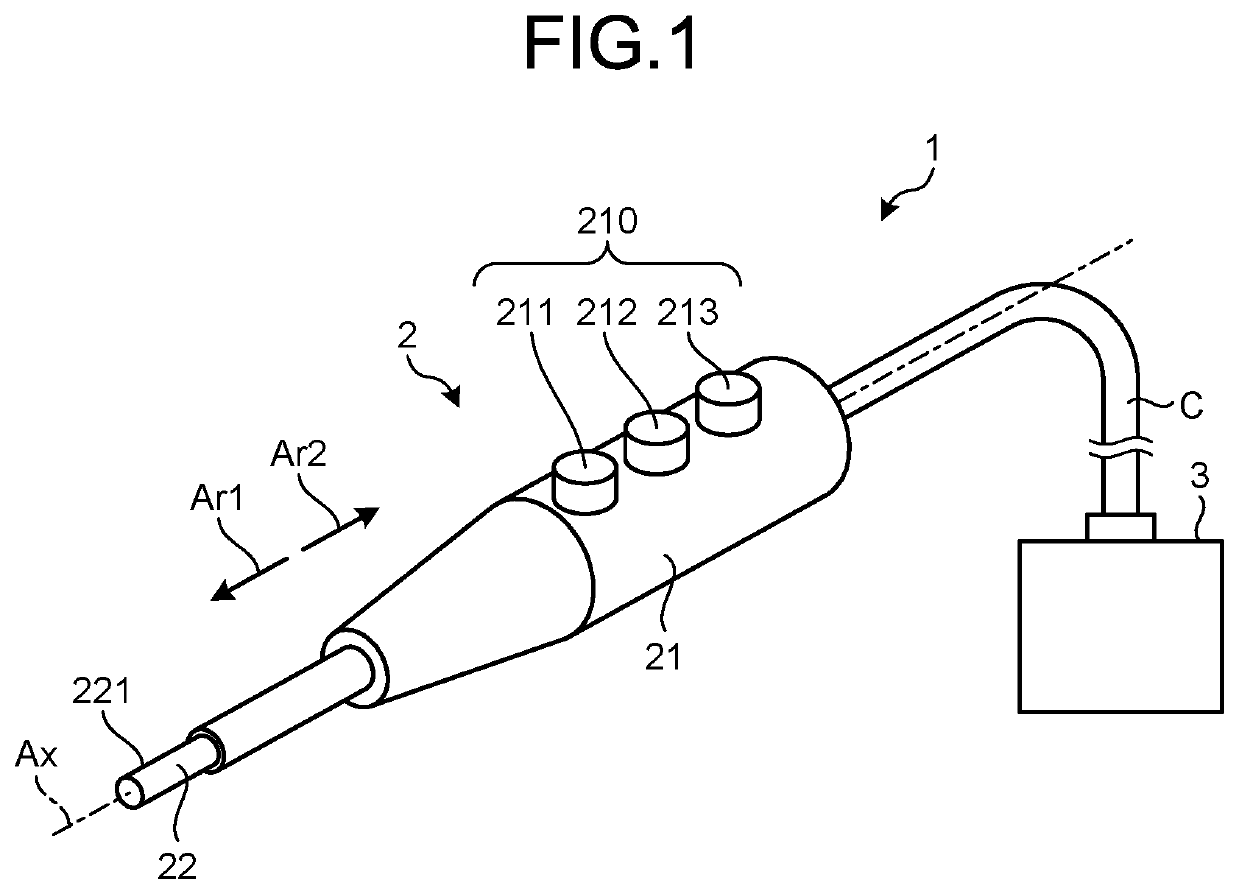
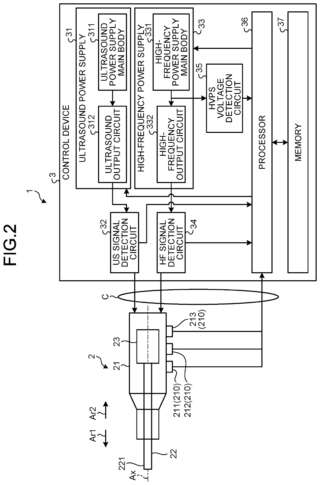
[0018]FIG. 1 is a diagram illustrating a medical system 1 according to a first embodiment. FIG. 2 is a diagram illustrating internal configurations of a treatment tool 2 and a control device 3.

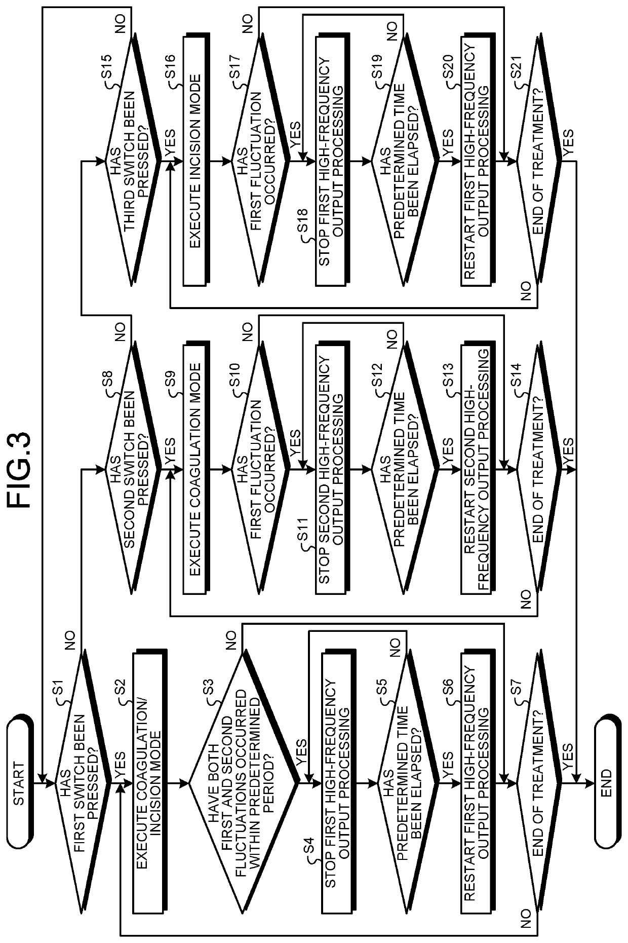
[0019]The medical system 1 applies ultrasound energy and high-frequency energy to a treatment target site (hereinafter, referred to as the target site) in a biological tissue, thereby treating the target site. Note that treatments that can be performed by the medical system 1 according to the first embodiment are three treatments, that is, a first treatment that performs both coagulation and incision of the target site, a second treatment that performs only the coagulation of the target site, and a third treatment that performs only the incision of the target site. The medical system 1 includes a treatment tool 2 and a control device 3, as illustrated in FIG. 1 or 2.

[0020]Configuration of Treatment Tool

[0021]As illustrated in FIG. 1 or 2, the trea...

second embodiment

[0109]Next, a second embodiment will be described.

[0110]In the following description, the same components as those in the first embodiment will be denoted by the same reference numerals, and detailed description thereof will be omitted or simplified.

[0111]In the first embodiment described above, a US impedance is adopted as a second index value according to the disclosure.

[0112]On the other hand, in the second embodiment, a mechanical load applied to an ultrasound probe 22 is adopted as the second index value according to the disclosure.

[0113]FIG. 5 is a diagram illustrating a medical system 1A according to the second embodiment.

[0114]Specifically, as illustrated in FIG. 5, the medical system 1A adopts a treatment tool 2A, which is a treatment tool 2 equipped with a force sensor 24, as compared with a medical system 1 described in the first embodiment.

[0115]The force sensor 24 is provided in a housing 21 and detects a mechanical load applied to an ultrasound probe 22. Then, the forc...


PUM


Abstract

A medical device includes: a high-frequency power supply configured to output a high-frequency signal to an end effector; a first detection circuit configured to detect a first index value; a second detection circuit configured to detect a second index value; and a processor configured to execute a first mode in which an output value of the high-frequency signal from the high-frequency power supply is reduced, when a fluctuation of the first index value detected by the first detection circuit occurs and a fluctuation of the second index value detected by the second detection circuit occurs. The high-frequency power supply includes a power supply main body and an output circuit configured to output the high-frequency signal by converting power output from the power supply main body, and the first detection circuit is configured to detect a voltage of the power supply main body as the first index value.

Description

CROSS-REFERENCE TO RELATED APPLICATION[0001]This application is a continuation of International Application No. PCT / JP2018 / 034668, filed on Sep. 19, 2018, the entire contents of which are incorporated herein by reference.BACKGROUND1. Technical Field[0002]The present disclosure relates to a medical device, a control method, and a computer-readable storage medium.2. Related Art[0003]In the related art, there is known a medical device that applies high-frequency energy to a biological tissue from an end effector by outputting a high-frequency signal to be high-frequency power to the end effector (for example, see International Publication No. 2013 / 042498).[0004]Here, in a case where an electroconductive member such as a metal forceps comes into contact with the end effector while treating the biological tissue, the high-frequency energy that should be used for the treatment of the biological tissue may be discharged, and treatment performance of the biological tissue may be deteriorate...

Claims


Application Information

Patent Timeline
Patent Type & Authority Applications(United States)
IPC IPC(8): A61B17/32
CPCA61B17/320092A61B2017/320082A61B2017/320095A61B18/12A61B17/320068A61B2017/00017A61B2017/0003
Inventor INABA, KIZUKU
Owner OLYMPUS CORP
Learn More