System and method for providing front-oriented visual information to vehicle driver

a technology for providing front-oriented visual information and vehicle drivers, which is applied in the field of visual displays, can solve the problems of reducing the safety of drivers, so as to minimize the risk, avoid the possibility of camera damage and/or a restricted field of view, and improve safety.

Active Publication Date: 2021-07-15
KLEAR VIEW CAMERA
View PDF0 Cites 2 Cited by
  • Summary
  • Abstract
  • Description
  • Claims
  • Application Information

AI Technical Summary

Benefits of technology

[0008]This system advantageously improves safety for vehicles moving into a line of traffic (turn) from a position that is perpendicular to the flow of that traffic and that are pulling out of a side street, building, garage or parking spot (merge). Often, such vehicles face hazards in performing these maneuvers because the driver must pull far enough forward to visually observe the near lane of traffic from his or her vantage point-which is typically several feet behind the front end of the vehicle. Illustratively, a protrusion of 4-6 feet or more is desirable in order for the driver to view the lane and determine whether to proceed or wait. During the movement to the protruded position, the front end of the car is vulnerable to being struck by other vehicles that are unseen to the driver, resulting in numerous accidents. The illustrative system and method provides a flush-mount or recessed camera at the specific location on the vehicle to minimize this hazard by transmitting an image of the scene of oncoming traffic to the driver from a vantage point that is essentially as far forward as possible.
[0009]Illustratively, in some embodiments, the camera is located in and is flush with the left front quarter panel. The front quarter panel is the outer portion of the vehicle forward of the passenger compartment along the left and right sides and typically includes a marker light and headlight assembly. The camera is generally free of any external protrusion relative to the vehicle body and / or its quarter panel, thereby avoiding potential damage to the camera and / or a restricted field of view. In some embodiments, the flush-mounted or recessed camera can image a field of view within an arc of approximately 90 degrees in both the horizontal and vertical axes (thereby defining a viewing cone). Other embodiments provide different cross sectional geometries—e.g. a geometry defining an elliptical cone with a wider horizontal axis. In various embodiments, an associated camera lens can define a field of greater or lesser than 90 degrees in the horizontal and / or vertical axes. In other embodiments, the system can allow the driver to select the desired angle and / or range of view via an interface or other adjustment mechanism within the vehicle. The camera can also include a preset or variable zoom lens, thereby allowing the driver to focus over a greater or lesser distance.

Problems solved by technology

The above described systems have a limited field of view and are easily damaged or knocked off the vehicle.
Likewise, they often require a dedicated display that adds further distraction to the driver.
In addition, such cameras often remain activated longer than needed.
Moreover, such cameras are not mounted to contemplate particular hazardous situations, such as the pull out into traffic to execute a turn or merge into traffic.
Often, such vehicles face hazards in performing these maneuvers because the driver must pull far enough forward to visually observe the near lane of traffic from his or her vantage point-which is typically several feet behind the front end of the vehicle.
During the movement to the protruded position, the front end of the car is vulnerable to being struck by other vehicles that are unseen to the driver, resulting in numerous accidents.

Method used


Image

  • System and method for providing front-oriented visual information to vehicle driver
  • System and method for providing front-oriented visual information to vehicle driver
  • System and method for providing front-oriented visual information to vehicle driver

Examples


Embodiment Construction

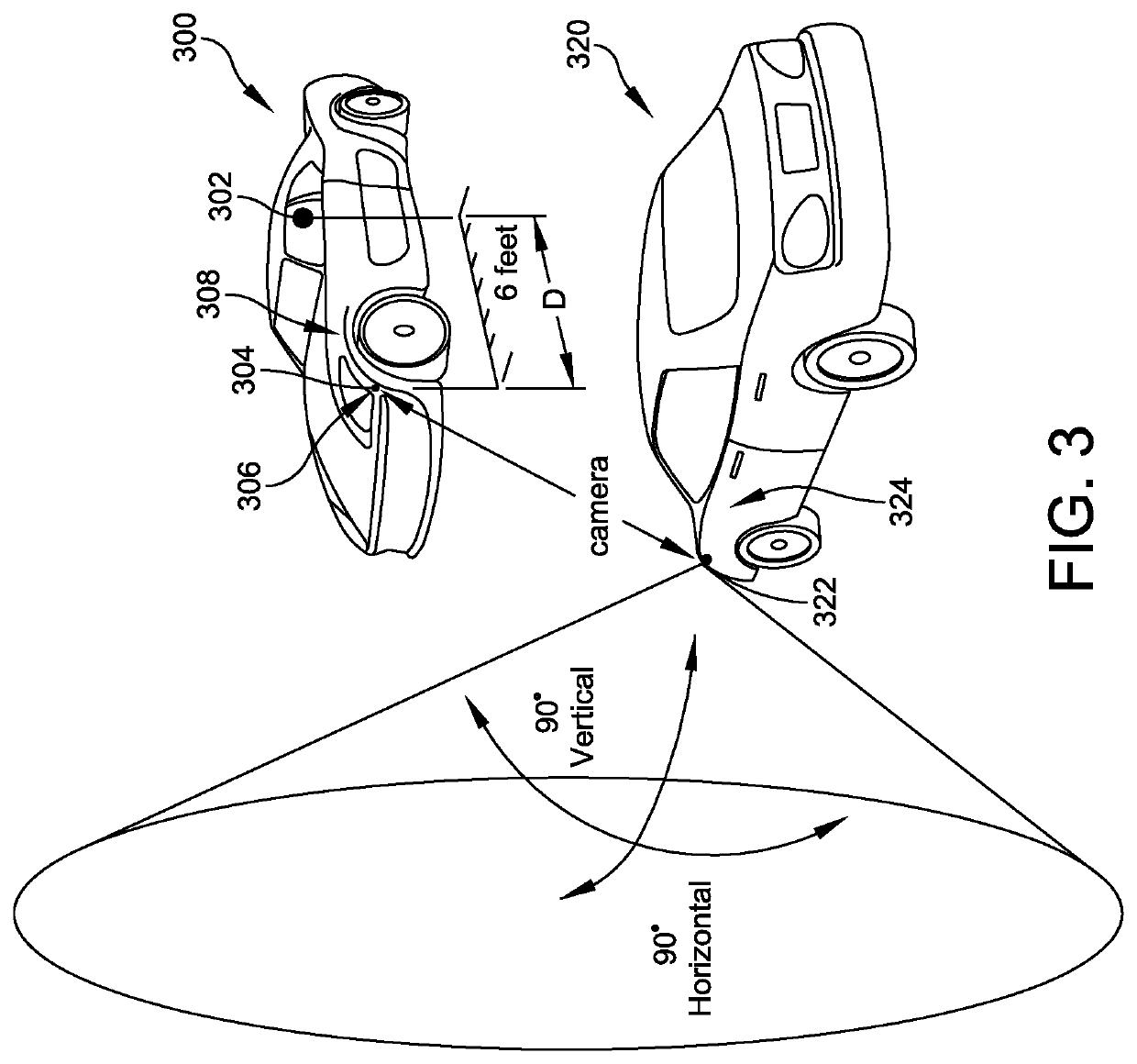
[0031]When a motor vehicle driver is situated so as to be perpendicular to the flow of traffic and pulling out of a side street, building, garage or parking spot, there is a danger to that driver and other operators. In order to see traffic in the oncoming lane, the driver has to pull far enough forward to visually observe the near lane of traffic. Other vehicles and objects placed along a roadway and other obstructions can prevent a clear view and necessitate a driver pulling forward into the near lane. Given that most vehicles have a front end that includes a motor or a storage compartment with a length of about 2-4 feet and that a driver typically sits another 2 feet or more from the dashboard, the driver may move the car until there is a protrusion of 4-6 feet or more, in order for the driver to view the lane and determine whether to proceed or wait. During the movement to the protruded position, the front end of the car is vulnerable to being struck by other vehicles that are u...


PUM


Abstract

A camera system is installed on the front end of a vehicle, either on the left front, the right front, or both sides. The camera is linked via wired or wireless connection to an onboard computer and a navigation display that is located within the passenger compartment of the vehicle. The driver reviews a visual description on the display of any oncoming traffic in the form of motor vehicles, pedestrians, cyclists, animals and the like on the navigation display via a single screen, split screen or alternating screens. The camera system can include a speed sensor that detects when the vehicle reaches a threshold speed to activate or de-activate the camera. Alternatively, the computer can activate the system when a turn signal is activated, and de-activate the system when the turn signal is no longer activated. This camera system can be retrofitted into older vehicles.

Description

RELATED APPLICATIONS[0001]This application is a continuation of U.S. patent application Ser. No. 16 / 696,205, filed Nov. 26, 2019, which is a continuation of U.S. patent application Ser. No. 15 / 368,099, filed Dec. 2, 2016, which is a continuation of U.S. patent application Ser. No. 14 / 428,881, filed Mar. 17, 2015, which is a 371 U.S. National Stage of International Application No. PCT / US2013 / 054828, filed Aug. 14, 2013, which is a continuation in part of U.S. patent application Ser. No. 13 / 587,548, filed Aug. 16, 2012, which claims the benefit of U.S. Provisional Application No. 61 / 592,505, filed Jan. 30, 2012, and this application claims the benefit of U.S. Provisional Application No. 61 / 860,573, filed Jul. 31, 2013, the entire disclosures of all said applications being expressly incorporated by reference herein.FIELD OF THE INVENTION[0002]This invention relates to vehicle safety devices, and more particularly to visual displays that enhance vehicle safety.BACKGROUND OF THE INVENTIO...

Claims


Application Information

Patent Timeline
Patent Type & Authority Applications(United States)
IPC IPC(8): B60R1/00B60K35/00G01C21/36B60Q9/00
CPCB60R1/00B60K2370/193G01C21/3697B60Q9/008B60R2300/70B60R2300/303B60R2300/105B60R2300/605B60R2300/406B60R2300/404B60R2300/302B60R2300/802B60K2370/168B60K2370/21B60K2370/179B60K2370/52B60K2370/152B60K2370/176B60K35/00B60Q1/0023B60K2370/589B60K2370/5905B60K2370/5911B60R1/28B60R1/25
Inventor PETRILLO, STEVEN R.ROEGER, ROBERT MICHAEL
Owner KLEAR VIEW CAMERA
Why Eureka
Try Eureka