
Image forming apparatus

Active Publication Date: 2021-07-22
SHARP KK
View PDF0 Cites 0 Cited by
  • Summary
  • Abstract
  • Description
  • Claims
  • Application Information

AI Technical Summary

Benefits of technology

The present invention relates to an image forming apparatus that can be shared by multiple groups of users. The invention allows spooled image data to be printed from users in different groups. This improves user convenience and allows for more efficient printing. Additionally, the invention allows for higher level users to print items of spooled image data that are sent from users in their own group. This enhances the security of the system and ensures that only authorized users can print. Overall, the invention provides a more convenient and secure image forming apparatus for multiple groups of users.

Problems solved by technology

In contrast, when an MFP having a spool function is shared in a shared workspace, a rented office space, or the like among users of multiple different groups, it is necessary to prevent users of other groups from printing the spooled image data due to problems regarding security, privacy, and the like.
As a result, there is a problem in that the waiting time extended, causing inconvenience to the user.

Method used


Image

  • Image forming apparatus
  • Image forming apparatus
  • Image forming apparatus

Examples


first embodiment

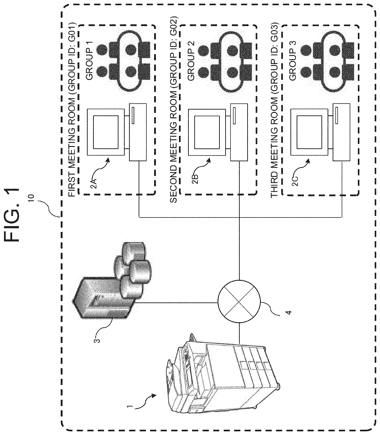
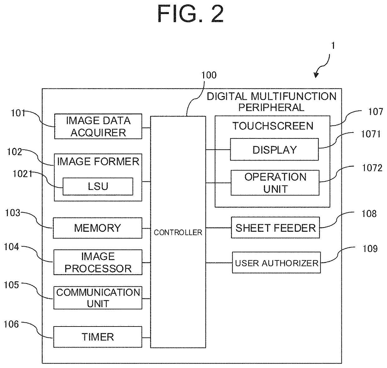
[0043]A schematic configuration of a digital multifunction peripheral 1, which is an embodiment of an image forming apparatus according to the present invention, will now be described with reference to FIGS. 1 and 2.

[0044]FIG. 1 is a diagram illustrating an example of the configuration of an image forming system 10 according to the present invention. FIG. 2 is a block diagram illustrating the schematic configuration of the digital multifunction peripheral 1 in FIG. 1.

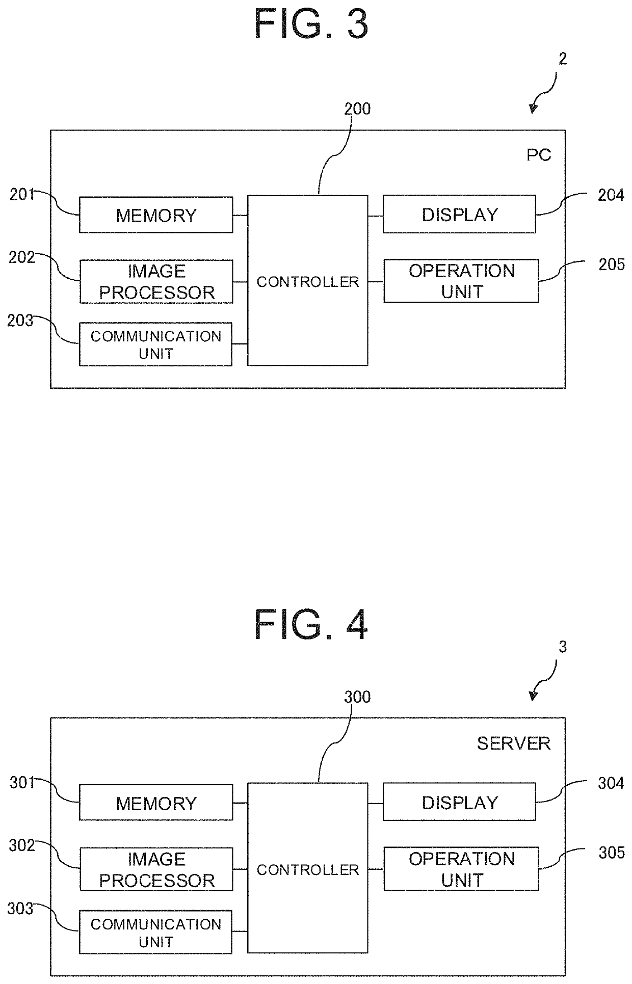
[0045]As illustrated in FIG. 1, the image forming system 10 of the present invention includes a digital multifunction peripheral 1, a PC 2A, a PC 2B, a PC 2C, and a server 3 connected to each other via a network 4.

[0046]Note that in the following description, the PC 2A, the PC 2B, and the PC 2C will be collectively referred to as “PCs 2.” However, the number of PCs 2 is not limited to three and may be any number.

[0047]In the example of FIG. 1, the PC 2A is installed in the first meeting room and used by the users of Gro...

second embodiment

[0134]An example of printing processing of spooled image data of the digital multifunction peripheral 1 according to the second embodiment of the present invention will now be described with reference to FIGS. 8 and 9.

[0135]FIG. 8 is an example of job data indicating the relationship between a job ID, a user ID, a password, a group ID, and a print sharing setting for the digital multifunction peripheral 1 according to the second embodiment of the present invention. FIG. 9 is a diagram illustrating an example of a selection menu of a spooled job of a digital multifunction peripheral 1 according to the second embodiment of the present invention.

[0136]In the second embodiment, it is possible to set whether or not the print sharing of spooled image data should be enabled between users of the same group.

[0137]The settings of “job ID,”“user ID,”“password,” and “group ID” in FIG. 8 are the same as those in FIG. 6 (first embodiment), but differ from that of the first embodiment in that ther...

third embodiment

[0144]An example of printing processing of spooled image data of the digital multifunction peripheral 1 according to the third embodiment of the present invention will now be described with reference to FIGS. 10 and 11.

[0145]FIG. 10 is an example of job data indicating the relationship between a job ID, a user ID, a password, a group ID, and a user authorization of a digital multifunction peripheral according to the third embodiment of the present invention. FIG. 11 is a diagram illustrating an example of a selection menu of a spooled job of a digital multifunction peripheral 1 according to the third embodiment of the present invention.

[0146]In the third embodiment, the authorization level of each user can be set.

[0147]The settings of “job ID,”“user ID,”“password,” and “group ID” in FIG. 10 are the same as those in FIG. 8 (second embodiment), but differ from that of the second embodiment in that further the “authorization” of each user can be set.

[0148]Each user has “lower” or “high...


PUM


Abstract

An image forming apparatus shared by users in multiple groups includes a communication unit, a memory, a user authorizer, an operation unit, a display, an image former, and a controller. When the operation unit accepts a command for forming an image from a first user based on spooled image data of the first user stored in a spool area in the memory after the user authorizer has authorized the first user, the controller causes the display to display, in addition to the spooled image data of the first user, spooled image data received by the communication unit, from other users belonging to the same group as the first user. When the operation unit accepts selection and a print command of the spooled image data, the controller causes the image former to collectively form images based on the selected spooled image data.

Description

BACKGROUND OF THE INVENTIONField of the Invention[0001]The present invention relates to an image forming apparatus.Description of the Background Art[0002]There has been known image forming apparatuses, such as multifunction peripherals (MFPs) that have a function (hereinafter referred to as “spool function”) for temporarily saving received image data in storage areas (hereinafter referred to as “spool areas”), such as hard disk drives (HDDs) of servers and MFPs, without immediate printing of the image data on sheets.[0003]In an MFP having such a spool function, the image data can be temporarily stored in the spool area without being printed on a sheet, to prevent the sheet from being left in the sheet tray for a long time.[0004]After logging in to the MFP, a user can instruct the printing of the image data stored in the spool area (spooled image data), to print the image data when necessary.[0005]When an MFP having such a spool function is to be used in a company office, a meeting r...

Claims


Application Information

Patent Timeline
IPC IPC(8): H04N1/32H04N1/00H04N1/44
CPCH04N1/32507H04N1/00244H04N2201/0094H04N1/4413H04N1/00413
Inventor KODAMA, HIROTAKA
Owner SHARP KK
Features
  • Generate Ideas
  • Intellectual Property
  • Life Sciences
  • Materials
  • Tech Scout
  • Unparalleled Data Quality
  • Higher Quality Content
  • 60% Fewer Hallucinations
Learn More