
Device for treating exhaust gases

Active Publication Date: 2021-07-29
VITESCO TECH GMBH
View PDF0 Cites 0 Cited by
  • Summary
  • Abstract
  • Description
  • Claims
  • Application Information

AI Technical Summary

Benefits of technology

The invention aims to improve exhaust gas treatment by making the device more tightly sealed.

Problems solved by technology

Some problems can be observed in the case of conventional heatable catalytic converters.
For 48-volt applications, resistances that are higher than usual are sometimes required and sometimes these cannot be technically implemented in the case of small substrate sizes since a minimum material length of the substrate has to be available.
Furthermore, problems may arise when inserting an insulated heating conductor.
Since the heating conductor is insulated, temperature distribution may be relatively poor.
In addition, closed cells may occur in the region of the heating conductor or an increased counterpressure may also occur.
Finally, problems may also arise when heating relatively large catalytic converter surfaces.
Electrical contacting by way of leading out each individual conductor track of heating elements through the outer wall of the device may be very complicated.
Furthermore, a thermomechanically stable carrier film coating is often associated with a great degree of process complexity.
The leaktightness of the device, for example with respect to escaping exhaust gases, can likewise be adversely affected by leading out the large number of individual electrical contacts.

Method used


Image

  • Device for treating exhaust gases
  • Device for treating exhaust gases
  • Device for treating exhaust gases

Examples


first embodiment

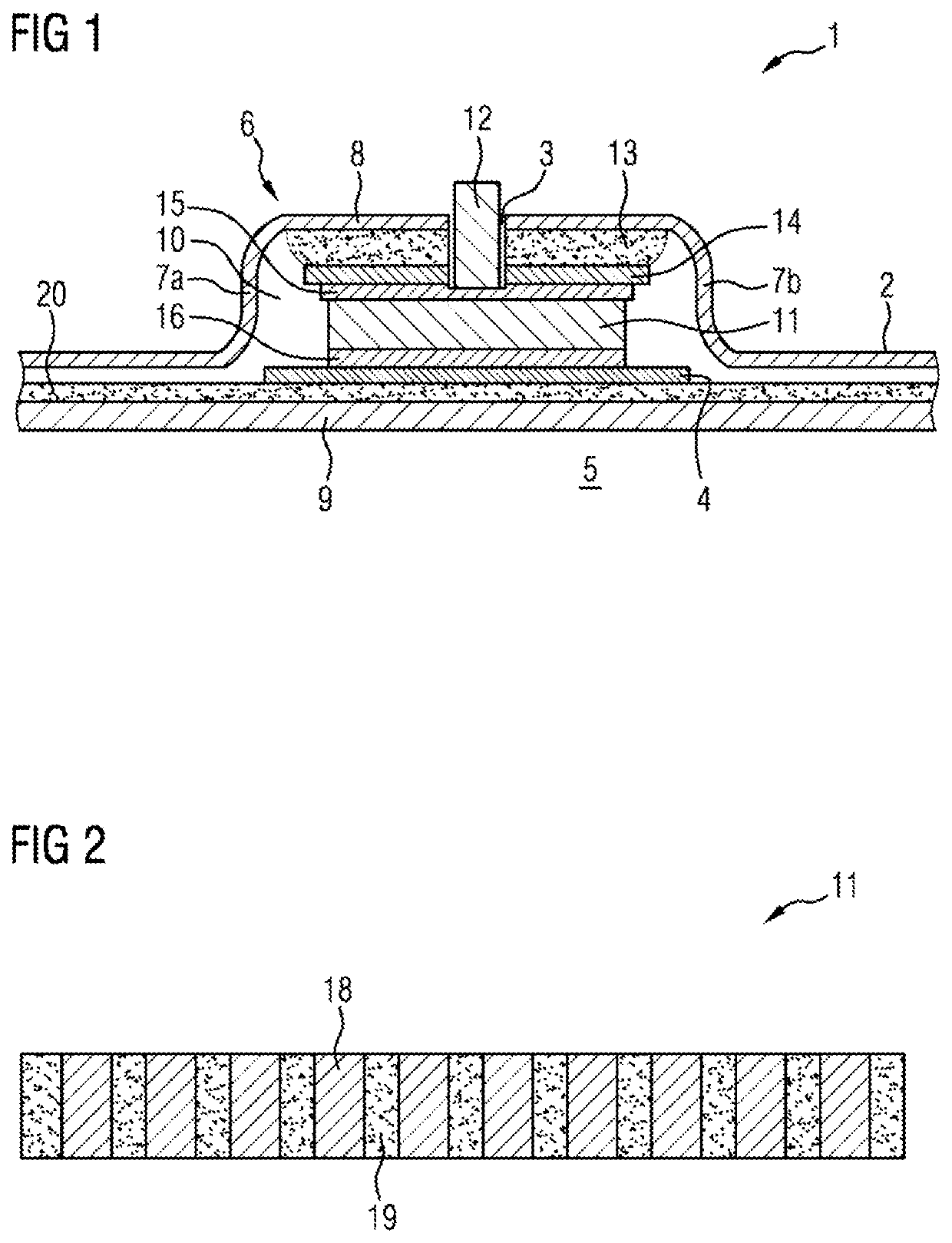
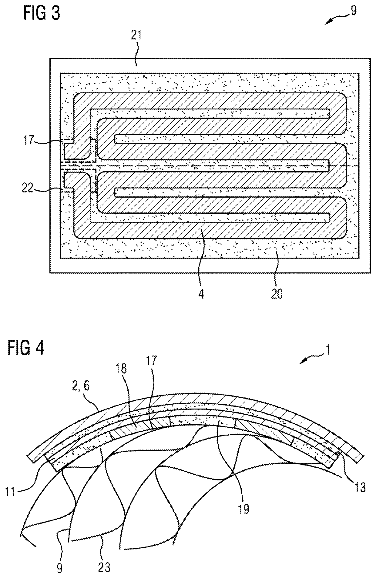
[0052]FIG. 1 shows a cross section through the device 1 according to the invention. The device 1 is a device for treating exhaust gases, here more precisely an areally heatable catalytic converter, as will become clearer below.

[0053]The device 1 has an outer wall 2. The outer wall 2 has an opening 3 in order to electrically contact a conductor track 4, which is arranged within an interior space 5 that is surrounded by the outer wall 2, through the outer wall 2. In the present exemplary embodiment, the outer wall 2 is of circular-cylindrical shape, wherein the circular-cylindrical curvature of the outer wall 2 is not illustrated in FIG. 1 for reasons of simplicity. An axis of symmetry of the circular-cylindrical outer wall 2 runs along the viewing direction of the illustration in FIG. 1.

[0054]The opening 3 is arranged in a projection 6 which protrudes outward from the interior space 5 and is integrally formed with the outer wall 2. Therefore, the projection 6 may replace a separate, ...

second embodiment

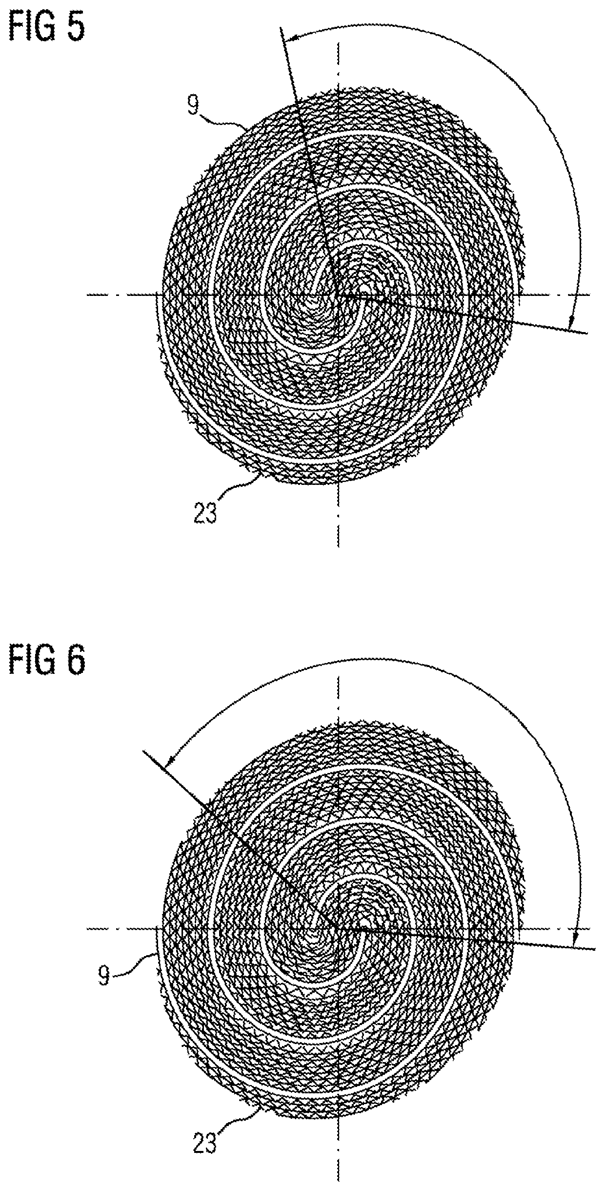
[0064]FIG. 6 shows a cross-sectional view along the axial viewing direction of the device 1 according to a The Figure shows a layer package including conductor track carriers 9 and corrugated layers 23 which has an alternative angle of tilt illustrated along a winding axis of the layer package. The winding of S-shape according to FIG. 6 is used for some embodiments of the invention that are not shown. It then simply replaces the winding according to FIG. 5, with adjustment of the electrode 11 and further elements which are dependent on the length of the layer termination. The direction of extent of the winding axis of the layer package shown again corresponds to the direction of extent of the axial extent of the outer wall 2. The layer package is again tilted, so that, in the non-wound, flat state, it forms the parallelogram when viewed from the end side. The layers are therefore once again arranged in a manner displaced in relation to one another. Here, by way of example, the angl...


PUM


Abstract

A device for treating exhaust gases which has an outer wall which has an opening in order to electrically contact one or more conductor tracks, which are arranged within an interior space that is surrounded by the outer wall, through the outer wall. The opening is arranged in a projection which protrudes outward from the interior space and is integrally formed with the outer wall.

Description

CROSS-REFERENCE TO RELATED APPLICATIONS[0001]This application claims priority to PCT Application PCT / EP2019 / 077571, filed Oct. 11, 2019, which claims priority to German Patent Application No. DE 10 2018 217 437.7, filed Oct. 11, 2018. The disclosures of the above applications are incorporated herein by reference.FIELD OF THE INVENTION[0002]The present invention relates to a device for treating exhaust gases which has an outer wall which has an opening in order to electrically contact one or more conductor tracks, which are arranged within an interior space that is surrounded by the outer wall, through the outer wall.BACKGROUND OF THE INVENTION[0003]Devices of this kind are known in principle, for example from EP 2 175 115 A1. The device for treating exhaust gases disclosed there has a sensor film which is embodied with a conductor element. A housing of the device has an opening for contacting the conductor element. In embodiments, provision is made to use the opening for contacting ...

Claims


Application Information

Patent Timeline
IPC IPC(8): B01D53/94H05B3/50
CPCB01D53/94H05B2203/024H05B2203/011H05B3/50F01N3/2026F01N3/281F01N13/1872F01N2240/16F01N2330/02F01N13/18Y02T10/12Y02T10/40Y02A50/20F01N9/00
Inventor HIRTH, PETERRINGS, FLORIAN
Owner VITESCO TECH GMBH
Learn More