
Printing device

a printing device and printing technology, applied in printing, printed circuit manufacture, conductive pattern formation, etc., can solve the problems of disadvantageous increase in the size of the stocker, difficult to significantly etc., to reduce or prevent an increase in the size of the printing device

Active Publication Date: 2021-07-29
YAMAHA MOTOR CO LTD
View PDF0 Cites 0 Cited by
  • Summary
  • Abstract
  • Description
  • Claims
  • Application Information

AI Technical Summary

Benefits of technology

The printing device described in this patent text can prevent its size from getting bigger because of an increase in the size of the mask replacement unit. In simpler terms, this means that the device can avoid becoming too big because of its mask.

Problems solved by technology

However, in the screen printing device described in Japanese Patent No. 2861332, the belt conveyor is arranged in the stocker in order to provide the take-in / take-out means configured to take the screen mask in / out from the stocker, and thus the size of the stocker is disadvantageously increased.
Therefore, there is a problem that it is difficult to significantly reduce or prevent an increase in the size of the printing device due to an increase in the size of the stocker (so-called mask replacement unit) that stores a mask to replace the screen mask.

Method used


Image

  • Printing device
  • Printing device
  • Printing device

Examples


first embodiment

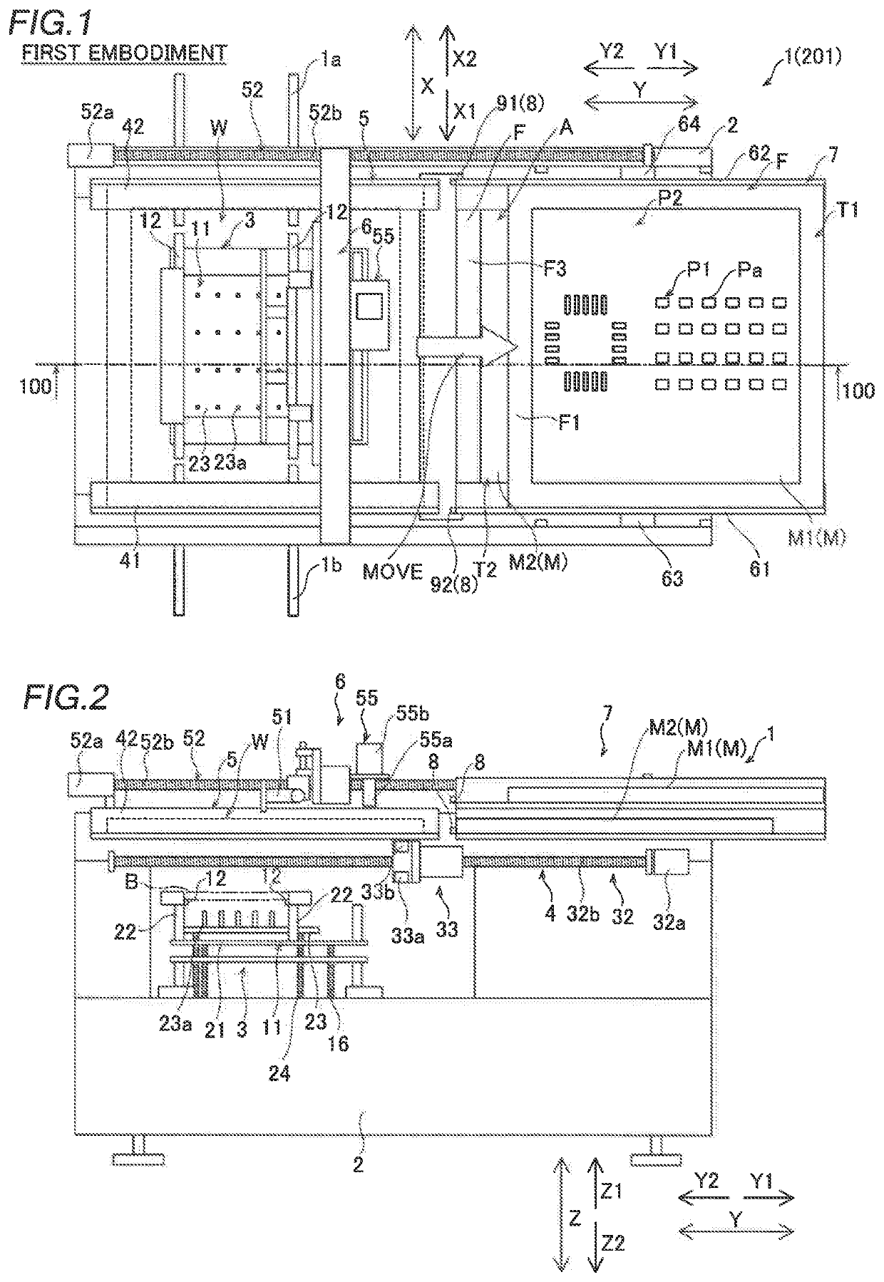
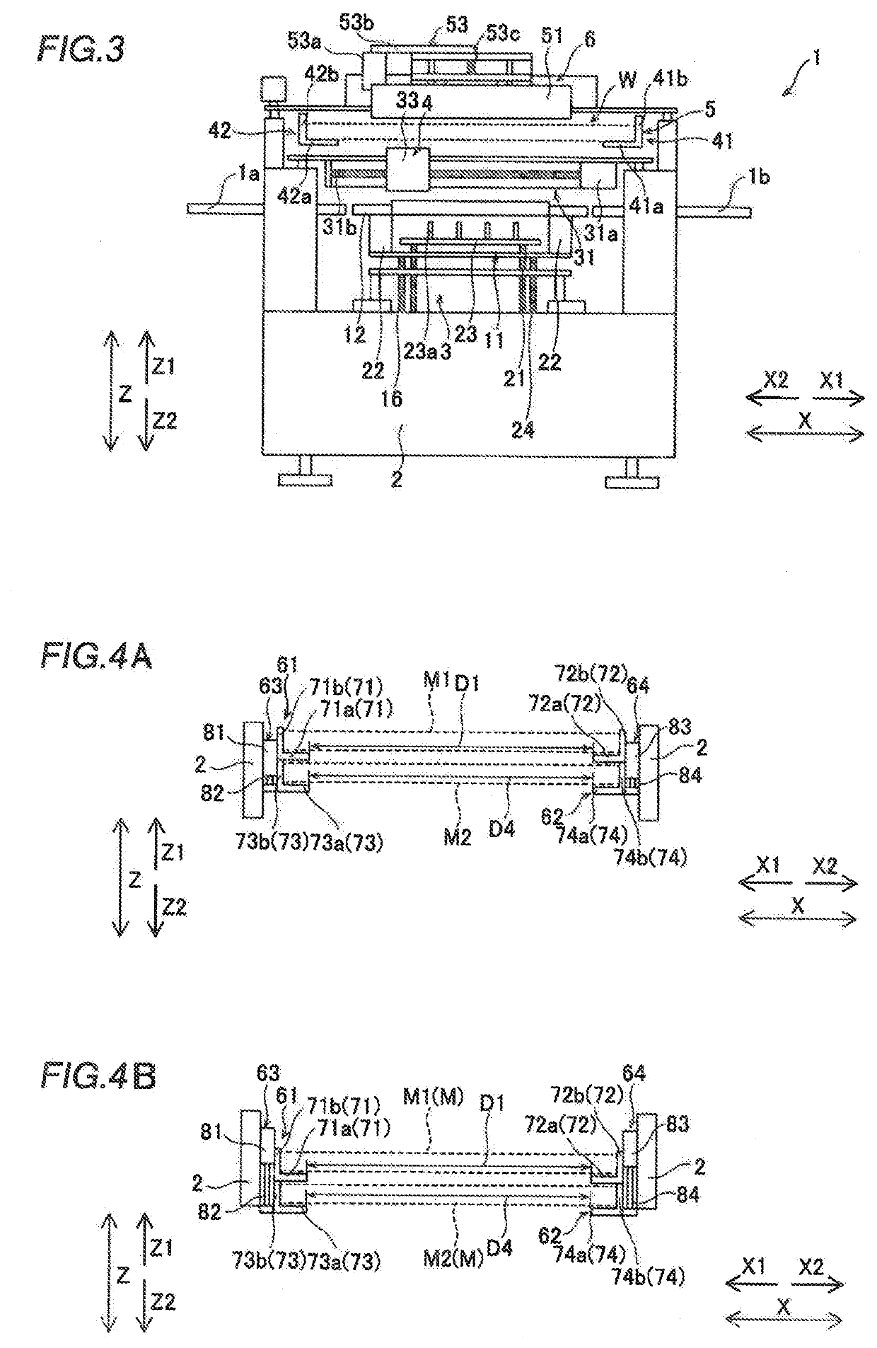
[0034]A printing device 1 according to a first embodiment of the present disclosure is now described with reference to FIGS. 1 to 9C. As shown in FIG. 1, the printing device 1 is a device that conveys a board B (see FIG. 2) in an X1 direction by a pair of conveyors 12 and prints solder on the board B in a printing position. The conveyance direction of the pair of conveyors 12 on which the board B is placed and the opposite direction are defined as an X direction, and a direction orthogonal to the X direction in a horizontal direction is defined as a Y direction. Furthermore, a direction orthogonal to the X direction and the Y direction is defined as a Z direction (upward-downward direction). The solder is an example of a “coating material” in the claims.

[0035]As shown in FIG. 1, the printing device 1 is configured to perform a printing process on a surface of the board B carried in by carry-in conveyors 1a with a predetermined pattern Pa of a plurality of openings P1 formed in a mas...

second embodiment

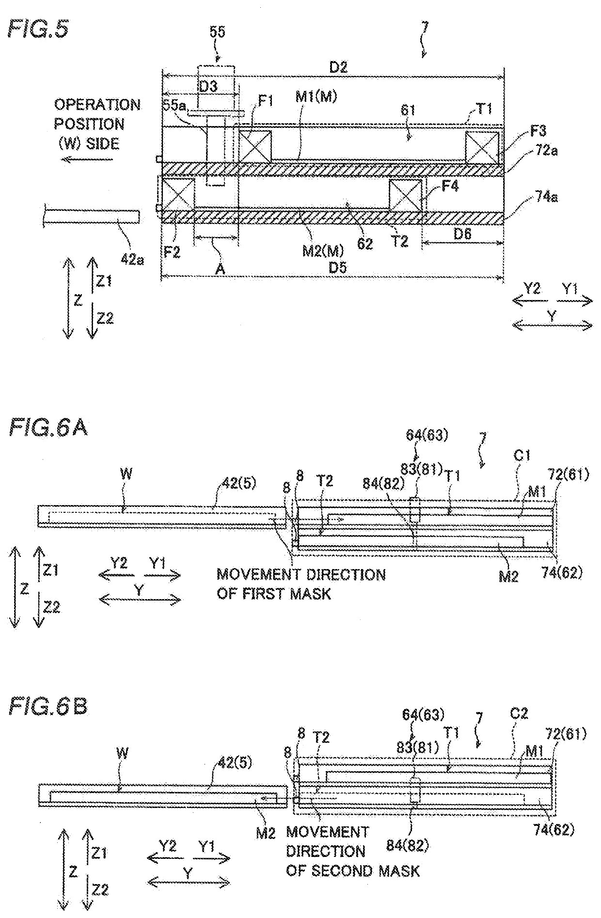
[0112]The structure of a printing device 201 according to a second embodiment of the present disclosure is now described with reference to FIGS. 1, 11, and 12. In the second embodiment, an example is described in which in a first predetermined position C1, the height of a first storage position T1 is lower than the height of an operation position W, and in a second predetermined position C2, the height of a second storage position T2 is higher than the height of the operation position W, unlike the first embodiment in which the height of the operation position W and the height of the first storage position T1 are substantially the same as each other in the first predetermined position C1, and the height of the operation position W and the height of the second storage position T2 are substantially the same as each other in the second predetermined position C2. In the second embodiment, the same or similar structures as those of the first embodiment are denoted by the same reference n...

modified examples

[0120]The embodiments disclosed this time must be considered as illustrative in all points and not restrictive. The scope of the present disclosure is not shown by the above description of the embodiments but by the scope of claims for patent, and all modifications (modified examples) within the meaning and scope equivalent to the scope of claims for patent are further included.

[0121]For example, while the example in which the ends of the first support 41a and the second support 42a of the mask clamp member 5 on the Y1 direction side have the end faces along the Z direction (upward-downward direction) has been shown in each of the aforementioned first and second embodiments, the present disclosure is not restricted to this. In the present disclosure, as in a first modified example shown in FIG. 13, ends of a first support 341a and a second support 342a of a mask clamp member 305 on the Y1 direction side may have inclined surfaces 325 inclined in a Z2 direction (downward direction) t...


PUM


Abstract

In a printing device, a second storage position is displaced from a first storage position so as to enable a moving member to move a second mask arranged in a second storage in a state in which a first mask is arranged in the first storage position by movement of the first mask from an operation position to the first storage position by the moving member.

Description

CROSS-REFERENCE TO RELATED APPLICATION[0001]This application is a National Stage of International Patent Application No. PCT / JP2018 / 021534, filed Jun. 5, 2018, the entire content of which is incorporated herein by reference.BACKGROUNDTechnical Field[0002]The present disclosure relates to a printing device, and more particularly, it relates to a printing device configured to print a coating material on a mask arranged in an operation position on a board arranged in a printing position.Background Art[0003]Conventionally, a printing device configured to print a coating material on a mask arranged in an operation position on a board arranged in a printing position is known. A printing device is disclosed in Japanese Patent No. 2861332, for example.[0004]Japanese Patent No. 2861332 discloses a screen printing device including a printing unit and a screen mask storage. The printing unit includes a screen mask, a mask holder that holds the screen mask, and a bracket that slides along rails...

Claims


Application Information

Patent Timeline
Patent Type & Authority Applications(United States)
IPC IPC(8): B41F15/08H05K3/12B41F15/36B41F15/44
CPCB41F15/0881H05K3/1233B41F15/44B41F15/36H05K3/1225B41F15/08
Inventor FUJIMOTO, TAKESHIPARK, JINOK
Owner YAMAHA MOTOR CO LTD
Learn More