
Testing device for an airbag module

a technology of airbag module and test device, which is applied in the direction of instruments, pedestrian/occupant safety arrangements, force/torque/work measurement apparatus, etc., can solve the problems of inability to use for further tests, high cost of prototype instruments, and high development process including instrument panels, so as to prevent damage or destruction of lids, and prevent noisy impacts of lids on support structures

Active Publication Date: 2021-07-29
MOTHERSON INNOVATIONS CO LTD
View PDF0 Cites 0 Cited by
  • Summary
  • Abstract
  • Description
  • Claims
  • Application Information

AI Technical Summary

Benefits of technology

The present invention provides a testing device for airbag systems that offers cost-efficient and reliable results. The device helps optimize airbag systems based on the instrument panel and installation situation without damaging the testing device. Additionally, the device can identify the best airbag module for a specific instrument panel.

Problems solved by technology

To develop optimized airbag systems expensive development processes including the instrument panels thus need to be carried out.
However, the use of prototype instruments is very costly since in each test the airbag cover of the instrument panel is torn open and thus the instrument panel destroyed so that it cannot be used for further tests anymore.
After testing the test device has to be costly repaired or completely replaced.
However, the testing device according to DE 10 2012 013 893 A1 is only partially be suited to simulate the installation situation of different instrument panels.

Method used


Image

  • Testing device for an airbag module
  • Testing device for an airbag module

Examples


first embodiment

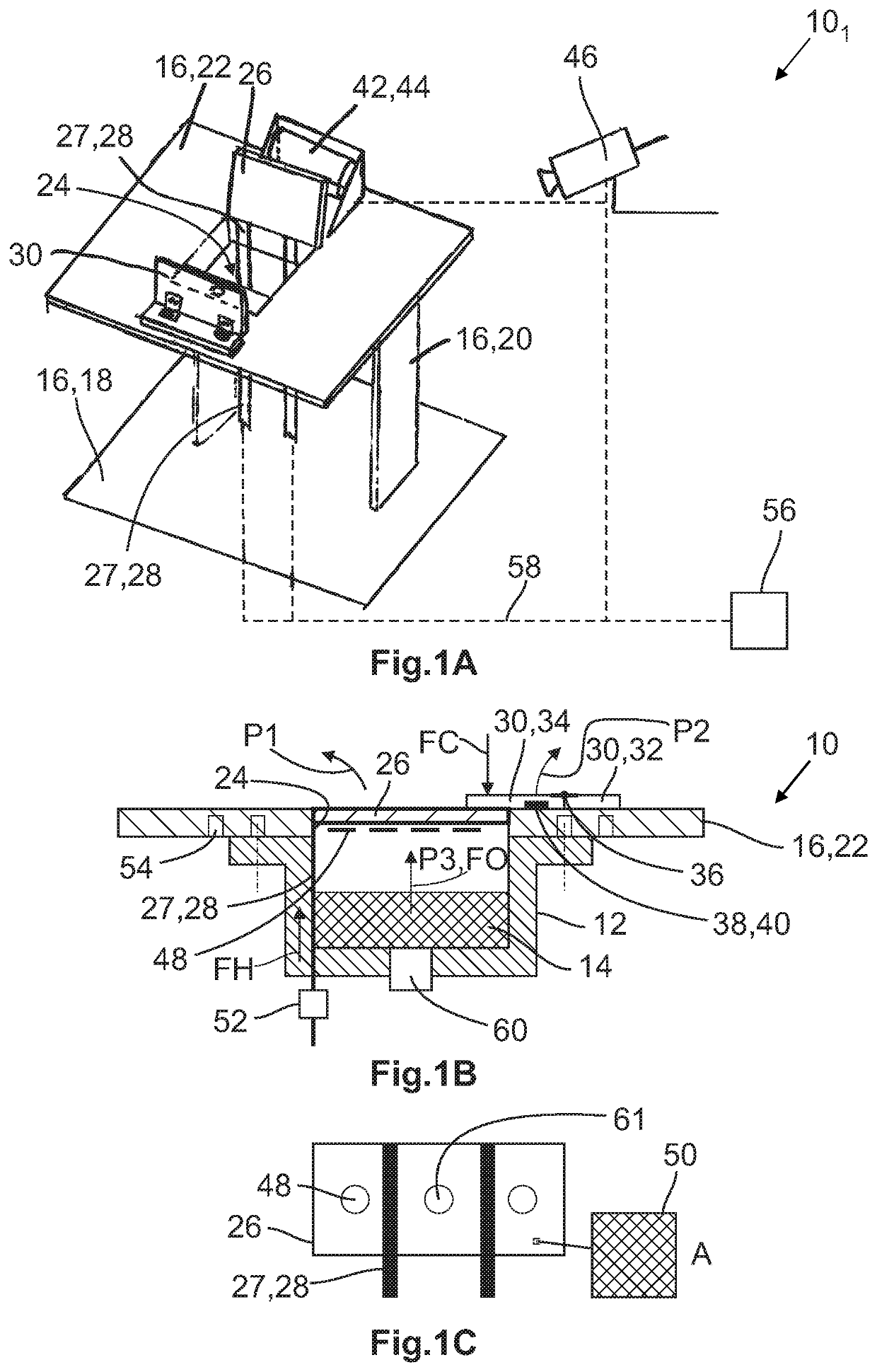
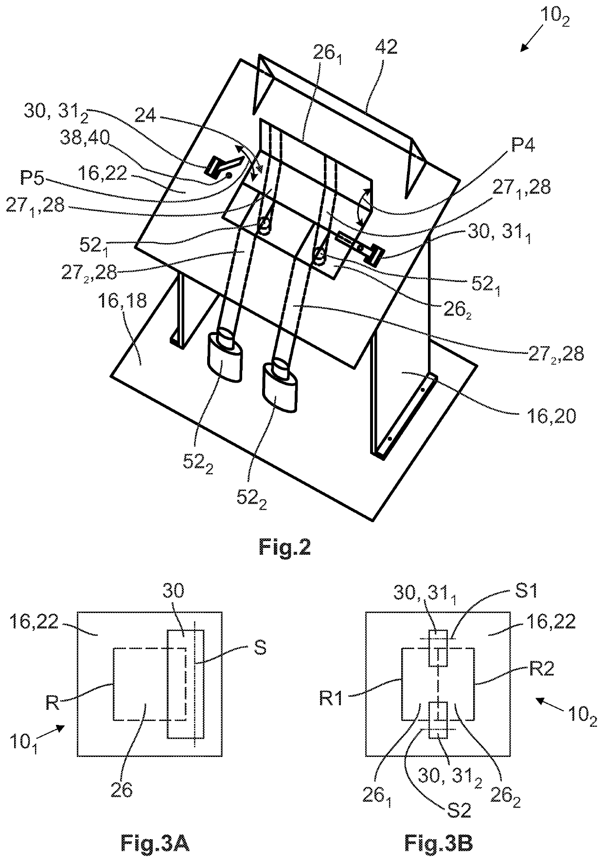
[0050]The passage 24 of the support structure 16 is covered by a first lid 261 and a second lid 262. The first lid 261 is fastened to the support structure 16 by two first fastening means 271 whereas the second lid 262 is fastened to the support structure 16 by two second fastening means 272. The fastening means 271, 272 can be designed as described with reference to the The way the first lid 261 moves when the airbag 14 is inflating is indicated by the arrow P4.

second embodiment

[0051]It is worth mentioning that the first fastening means 271 is equipped with a first group of second force sensors 521 while the second fastening means 272 comprises a second group of second force sensors 522. In the second embodiment shown in FIG. 2 each group 521, 522 consists of two second force sensors 52. The number of second force sensors 52 can be varied if considered beneficial.

[0052]The closure device 30 comprises a first sub-unit 311 and a second sub-unit 312. They are arranged such that they partially cover the first lid 261 and the second lid 262 when in the closing position. The way the second sub-unit 312 is moving when the airbag 14 is inflating is indicated by the arrow P5.

[0053]For the sake of clarity, the computer 56 and the cables 58 are not shown. However, the accelerations and forces acting on the first lid 261 and the second lid 262 can be detected and analyzed in the same way as described for the first embodiment. One difference is that the behavior of the...


PUM


Abstract

A testing device for an airbag module includes a support structure to which an airbag module containing an airbag can be fastened, the support structure forming a passage which can be penetrated by the airbag, at least one lid movably fastened to the support structure by fastening means between a closing position in which the lid closes the passage and an open position in which the passage is opened, and a closure device that closes the lid in the closing position by applying a closing force to the lid, wherein the lid comprises at least one first force sensor measuring the opening force applied to the lid by the airbag when moved out of the closed position by the airbag.

Description

CROSS-REFERENCES TO RELATED APPLICATIONS[0001]This application claims the priority of European Patent Applications Serial No. 20 153928.5, filed Jan. 27, 2020 and 20 178227.3, filed Jun. 4, 2020 pursuant to 35 U.S.C. 119(a)-(d), the subject matter of which is incorporated herein by reference.BACKGROUND OF THE INVENTION[0002]The present disclosure relates to a testing device for an airbag module.[0003]The airbags of a vehicle, in particular the passenger airbag, are arranged in a folded way inside an airbag module located invisibly to the vehicle passenger. In case of passenger airbags they are mounted behind the instrument panel. The instrument panel comprises an airbag cover, also referred to as airbag flap closing a chute channel mainly defined by the airbag module. The airbag module comprises a gas generator that when triggered provides high pressure gas that is introduced into the airbag which is thereby inflated. The airbag cover of the instrument panel is subsequently torn ope...

Claims


Application Information

Patent Timeline
IPC IPC(8): G01M17/007G01M7/08G01L5/00
CPCG01M17/0078G01L5/0052G01M7/08G01M17/007G01L17/00B60R21/16B60R21/215G01M99/008
Inventor BAL, ERKANBADER, ALEXANDERKUEGEL, LUKASFORSTHOFER, KONRAD
Owner MOTHERSON INNOVATIONS CO LTD
Learn More