
Methods of operating an agricultural sprayer

a sprayer and agricultural technology, applied in the field of agricultural sprayers, can solve the problems of increasing the cost level of sprayer operators and the need for sprayers to return to centralized locations, and achieve the effect of simple and cost-effective mechanisms

Inactive Publication Date: 2021-08-05
AGCO CORP +1
View PDF8 Cites 1 Cited by
  • Summary
  • Abstract
  • Description
  • Claims
  • Application Information

AI Technical Summary

Benefits of technology

[0008]The use of ozone allows for a relatively simple and cost-effective mechanism for the cleaning of agricultural sprayers as well as the sterilization of the spay liquid used in such sprayers. It will be understood that the spray liquid may comprise a fertilizer chemical, or any known pesticide, herbicide or fungicide used for crop protection. It will be understood that the spray liquid itself does not comprise ozone.
[0034]The use of ozone allows for a relatively simple and cost-effective mechanism for the cleaning of agricultural sprayers as well as the sterilization of the spay liquid used in such sprayers. It will be understood that the spray liquid may comprise any known pesticide, herbicide, or fungicide used for crop protection, or any suitable liquid fertilizer. Preferably, the agricultural sprayer comprises a self-propelled sprayer apparatus, but it will be understood that the invention may also apply to a tractor-mounted spray system, e.g., for use as a hitch-mounted implement or as a towed sprayer system.

Problems solved by technology

However, such excessive use of water and cleaning solutions can be relatively wasteful, as well resulting in increased cost levels for sprayer operators.
In addition, sprayers can often be required to return to a centralized depot for a cleaning operation, if the relatively large volumes of rinse water or cleaning solutions are too bulky to transport with the sprayer itself.

Method used


Image

  • Methods of operating an agricultural sprayer
  • Methods of operating an agricultural sprayer
  • Methods of operating an agricultural sprayer

Examples


Embodiment Construction

[0057]The illustrations presented herein are not actual views of any combine harvester or portion thereof, but are merely idealized representations to describe example embodiments of the present disclosure. Additionally, elements common between figures may retain the same numerical designation.

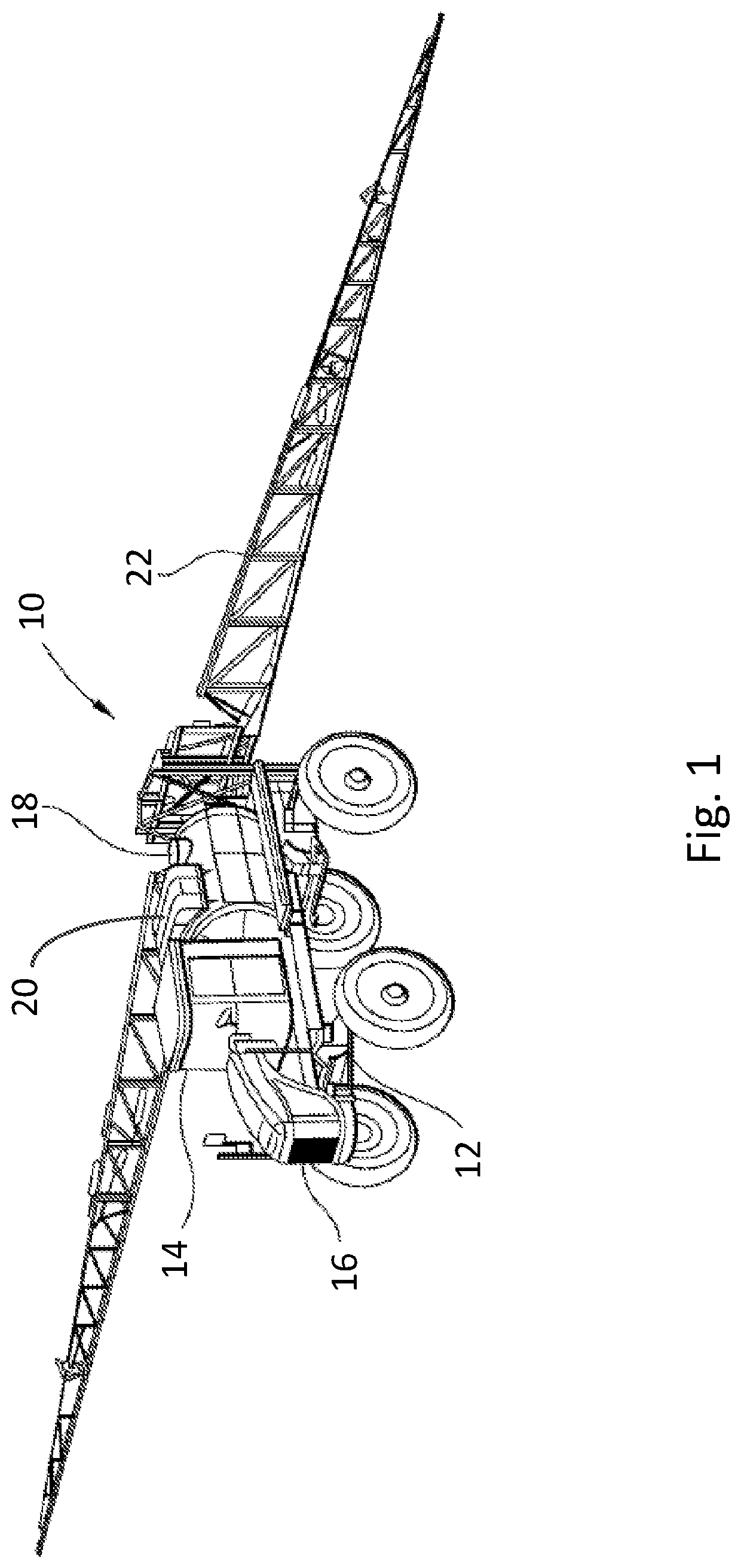
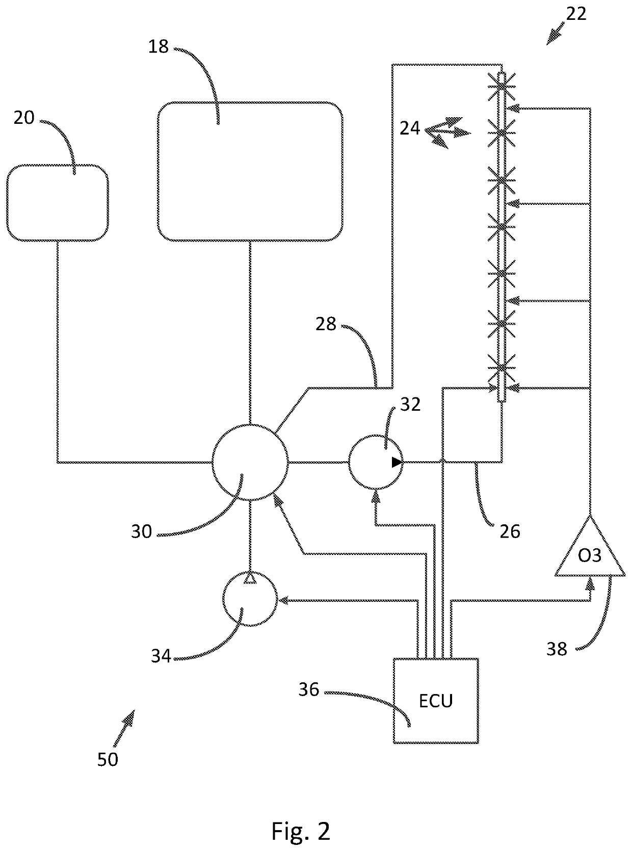
[0058]FIG. 1 shows an agricultural crop sprayer 10 used to deliver chemicals to agricultural crops in a field. Agricultural sprayer 10 comprises a chassis 12 and a cab 14 mounted on the chassis 12. Cab 14 may house an operator and a number of controls for the agricultural sprayer 10. An engine 16 may be mounted on a forward portion of chassis 12 in front of cab 14 or may be mounted on a rearward portion of the chassis 12 behind the cab 14. The engine 16 may comprise, for example, a diesel engine or a gasoline powered internal combustion engine. The engine 16 provides energy to propel the agricultural sprayer 10 and also can be used to provide energy used to spray fluids from the sprayer 10.

[00...


PUM


Abstract

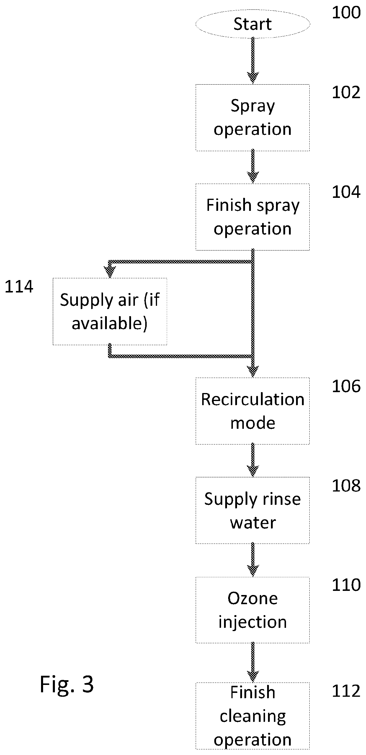
An agricultural sprayer includes an ozone supply arranged to clean at least a portion of the sprayer after a spraying operation has been completed, by supplying ozone to the residual spray liquid and to the interior of the sprayer plumbing. The ozone supply may be preceded by a rinsing or flushing of the sprayer plumbing using a rinse fluid, with the ozone injected to a circulating fluid in the sprayer plumbing. The sprayer may have an auxiliary liquid tank, such that residual spray liquid may be drained to the auxiliary tank to be cleaned using ozone. Such a cleaning operation can be performed at the same time as a further spraying operation, thereby providing for improved efficiency of operation of the sprayer.

Description

CROSS-REFERENCE TO RELATED APPLICATIONS[0001]This application is divisional of U.S. patent application Ser. No. 15 / 781,337, which is a national phase entry under 35 U.S.C. § 371 of International Patent Application PCT / IB2017 / 000228, filed Jun. 4, 2018, designating the United States of America and published in English as International Patent Publication WO 2017 / 168227 A1 on Oct. 5, 2017, which claimed the benefit of the filing date of U.S. Provisional Patent Application 62 / 314,611, filed Mar. 29, 2016, the entire disclosure of each of which is incorporated herein by reference.FIELD[0002]The present invention relates to an agricultural sprayer and a method of operating such a sprayer.BACKGROUND[0003]Agricultural sprayers are used in the application of various materials to field crops. Such systems apply various chemicals in the form of a spray for the purposes of crop protection, e.g., through the use of appropriate pesticides or herbicides, or for the purposes of promoting plant grow...

Claims


Application Information

Patent Timeline
Patent Type & Authority Applications(United States)
IPC IPC(8): B05B1/20A01M7/00A01C23/04
CPCB05B1/20A01M7/0042A01M7/0089A01C23/047A01M7/005
Inventor ZIMMERMAN, JEFFREY M.HIDDEMA, JORIS JAN
Owner AGCO CORP
Learn More