
Car Mat Structures

Inactive Publication Date: 2021-08-05
FORMOSA SAINT JOSE
View PDF0 Cites 4 Cited by
  • Summary
  • Abstract
  • Description
  • Claims
  • Application Information

AI Technical Summary

Benefits of technology

The invention is about new car mat structures that are designed to hold waterdrops or debris. These structures include a bottom pad with sidelines and raised dams. The dams have inclined surfaces at different angles, and triangle shutters are added to cover the bottom corners. These new designs make it easier to mold and clean the mats, and they help prevent deformation or collapsing. Additionally, an inclined cover pad can be added for even better efficiency in production and cleaning.

Problems solved by technology

However, every known existing car mat in the market or being used is basically a plastic product with a nearly 90 degree angle connection from its side wall to its bottom surface that inevitably leave a crevice or gap in between the side wall and the foot resting area in the car chamber applying the car mat.
What can be worse is that the side wall of the mat suffers deformation or even collapsing inwardly after being used for a period of time, not only causing tremendous trouble or inconvenience, but also greatly affect driving and put the driver, the passenger, and even the passersby or other cars on the road in great and unpredictable danger.
Moreover, due to the almost 90 degree connection of the wall with the bottom surface of the mat, deformation in the connection part and in the bottom angle portion formed by 2 connecting walls with the bottom surface is generally severe, and cleaning of them becomes even more difficult.

Method used


Image

  • Car Mat Structures
  • Car Mat Structures
  • Car Mat Structures

Examples


Embodiment Construction

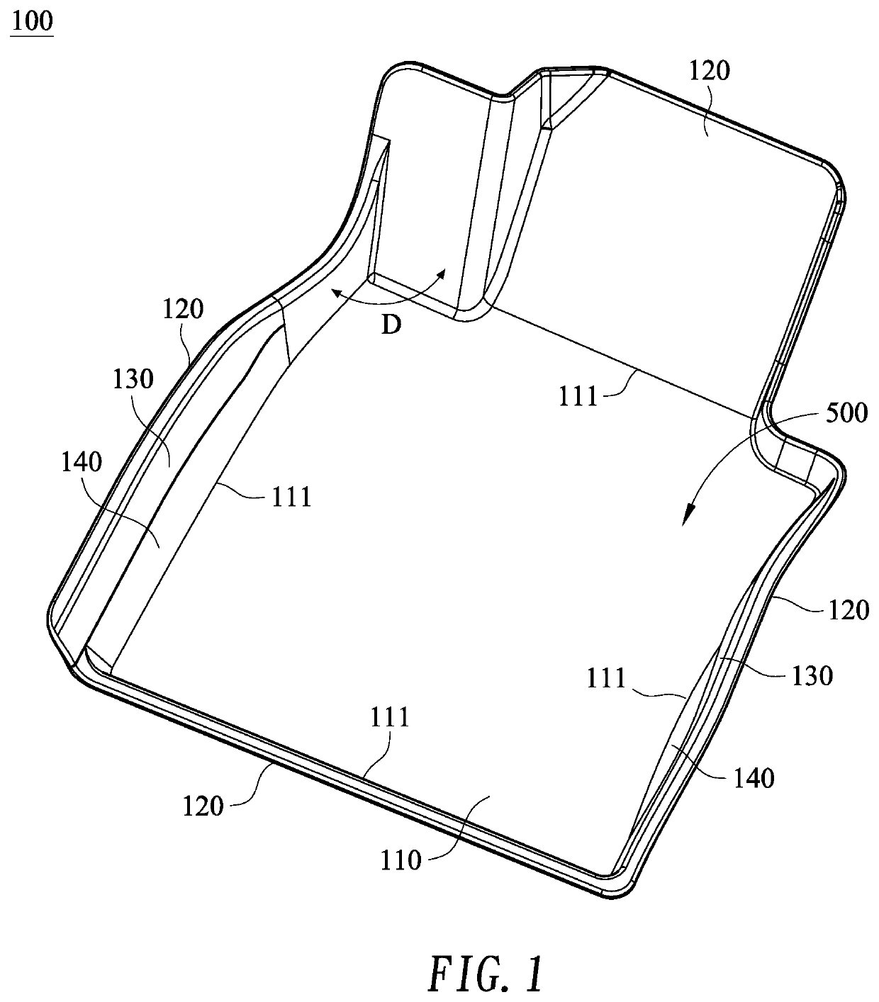
[0034]Please refer to FIG. 1, in an embodiment of the present invention, a car mat structure 100, used to set firmly on the foot resting area of a car, includes a bottom pad 110 and plural dams 120.

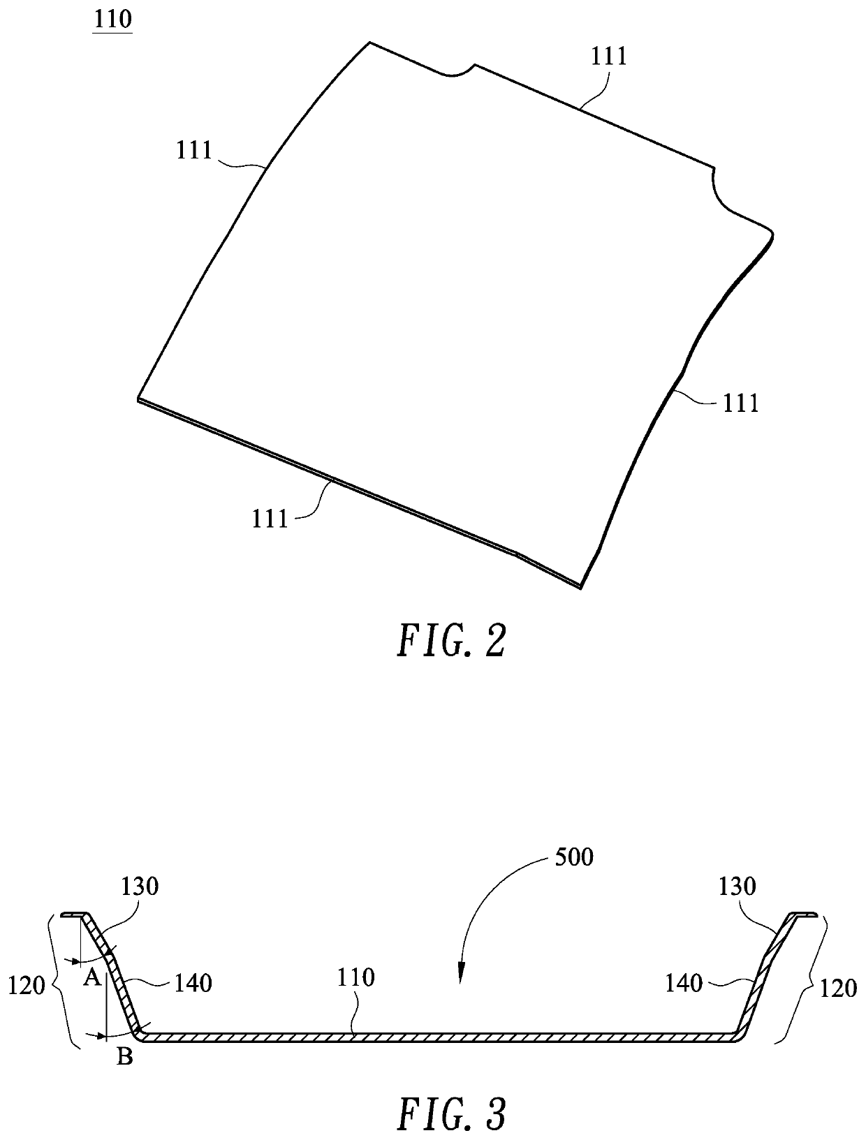
[0035]As shown in FIG. 1 and FIG. 2, the bottom pad 110, being formed as a pad with plural sidelines 111, has no restriction in the number of the sidelines 111. However, there can be 4 sidelines 111 on the bottom pad 110, and when the number of the sidelines 111 is 4, the angle D between any two adjacent sidelines is nearly 90 degrees.

[0036]The forming material for the bottom pad 110 can be plastic, polymer, or other material that is light, tough, water proof, or easy to be cleaned. While the shape, color or the thickness required are all chosen to meet the application requirements of different car types.

[0037]As can be seen in the embodiment shown in FIG. 1 and FIG. 3, plural dams 120, being raised walls each shaped and formed on a sideline 111, side-to-side connecting each other to surr...


PUM


Abstract

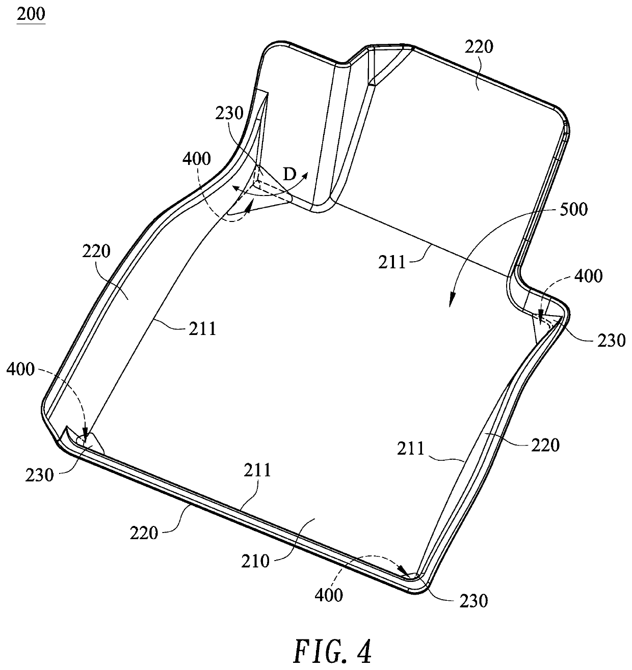
The present invention discloses car mat structures used to set on the floor compartment area in a car to contain water drops or debris fallen or brought into the car. One car mat structure includes a bottom pad with plural sidelines; and plural dams, each being raised from one said sideline, wherein two opposite members of the dams are dual slop walls each being built with two inclined surfaces with different inclined angles. Another car mat structure includes a bottom pad; plural dams raised from the sidelines of the bottom pad; and plural triangle shutters formed to cover bottom corners each formed by two adjacent dams and the bottom pad. A third car mat structure includes a bottom pad; plural dams raised from the sidelines of the bottom pad, wherein two opposite members of the dams each being built with two inclined surfaces with different inclined angles; and plural triangle shutters. With the implementation of the new design dams and triangle shutters of the present invention, molding is easier when forming and producing mat structures; cleaning becomes easier since no hidden corners existing on the mat structures; and deformation or collapsing of mat structures being effectively prevented. When further build an inclined cover pad to cover the junction area between a dam and the bottom pad, molding for production and cleaning the mats become even more convenient and efficient.

Description

BACKGROUND OF THE INVENTION1. Technical Field[0001]The present invention relates to mat structures, and more particularly, to car mat structures for car applications.2. Description of Related Art[0002]Being important and necessary equipment on a car, car mats are widely used nowadays. Car users normally have more than one set of car mats for different environment conditions. When set on the foot resting area inside a car, car mats are used to be a buffer, or more importantly, used to contain water drops or debris fallen into the car chamber.[0003]However, every known existing car mat in the market or being used is basically a plastic product with a nearly 90 degree angle connection from its side wall to its bottom surface that inevitably leave a crevice or gap in between the side wall and the foot resting area in the car chamber applying the car mat.[0004]What can be worse is that the side wall of the mat suffers deformation or even collapsing inwardly after being used for a period ...

Claims


Application Information

Patent Timeline
IPC IPC(8): B60N3/04
CPCB60N3/048B60N3/044
Inventor YANG, MING-SHUN
Owner FORMOSA SAINT JOSE
Learn More