
Method of forming a structure including carbon material, structure formed using the method, and system for forming the structure

a technology of carbon material and forming method, applied in the direction of coating, chemical vapor deposition coating, metallic material coating process, etc., can solve the problems of increasing the difficulty of applying conventional carbon material deposition techniques to manufacturing processes, affecting the quality of carbon materials, and affecting the appearance of carbon materials

Pending Publication Date: 2021-08-05
ASM IP HLDG BV
View PDF5 Cites 114 Cited by
  • Summary
  • Abstract
  • Description
  • Claims
  • Application Information

AI Technical Summary

Benefits of technology

The present patent provides improved methods for forming structures suitable for use in electronic devices. The methods involve the use of carbon material and plasma, and can be performed using an inert gas. The methods can involve forming a plasma in a reaction chamber and then using activated species to treat the carbon material. The resulting structures have improved properties, such as higher carbon content and fewer particles. The methods can be performed using a system that includes a reaction chamber, plasma generator, and inert gas supply. The technical effects of the patent include improved methods for forming high-quality carbon structures suitable for electronic devices.

Problems solved by technology

For example, during deposition of carbon material, such as techniques that include plasma processes, voids can form within the deposited material, particularly within gaps.
As device and feature sizes continue to decrease, it becomes increasingly difficult to apply conventional carbon material deposition techniques to manufacturing processes, while obtaining desired fill capabilities and material properties.
Further, various attempts to deposit carbon material on a surface of a substrate have led to undesirable amounts of particles on a substrate surface.

Method used


Image

  • Method of forming a structure including carbon material, structure formed using the method, and system for forming the structure
  • Method of forming a structure including carbon material, structure formed using the method, and system for forming the structure
  • Method of forming a structure including carbon material, structure formed using the method, and system for forming the structure

Examples


Embodiment Construction

[0023]Although certain embodiments and examples are disclosed below, it will be understood by those in the art that the invention extends beyond the specifically disclosed embodiments and / or uses of the invention and obvious modifications and equivalents thereof. Thus, it is intended that the scope of the invention disclosed should not be limited by the particular disclosed embodiments described below.

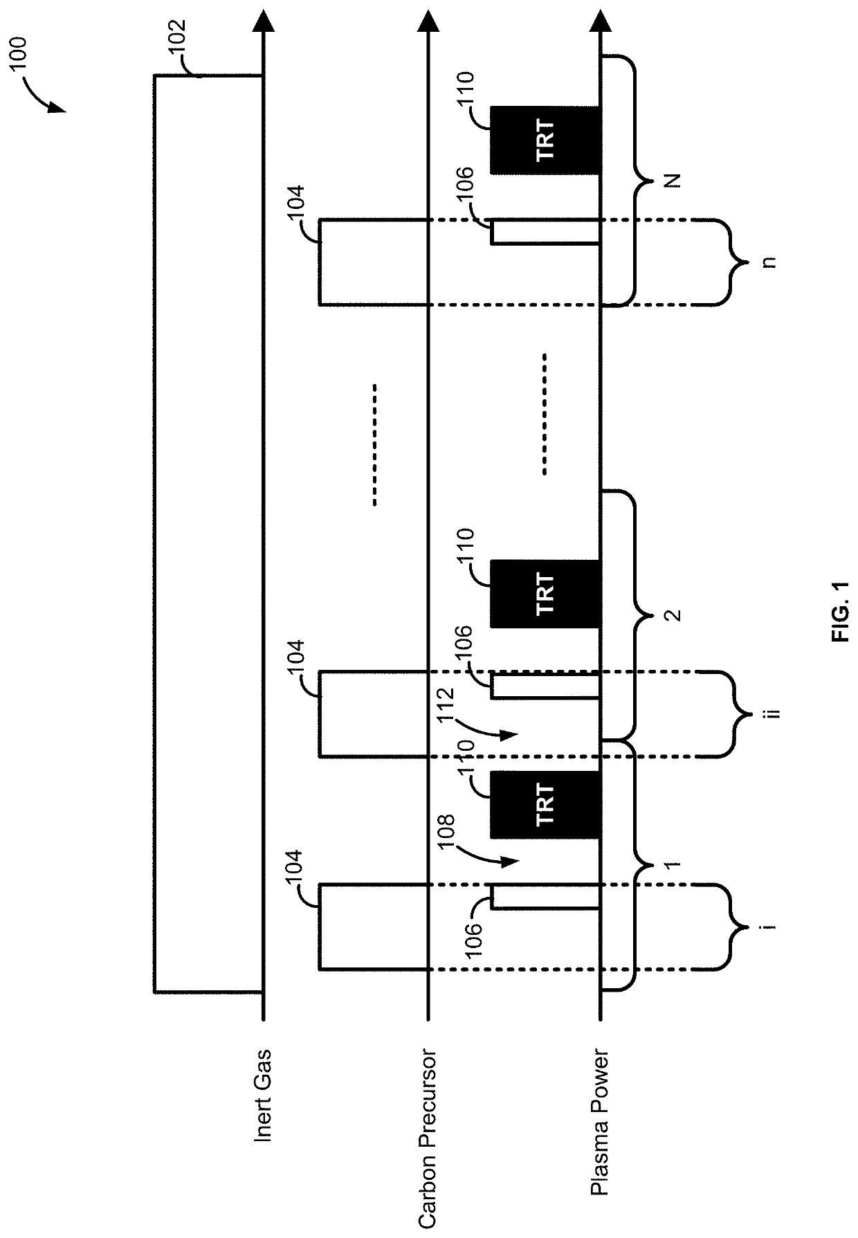
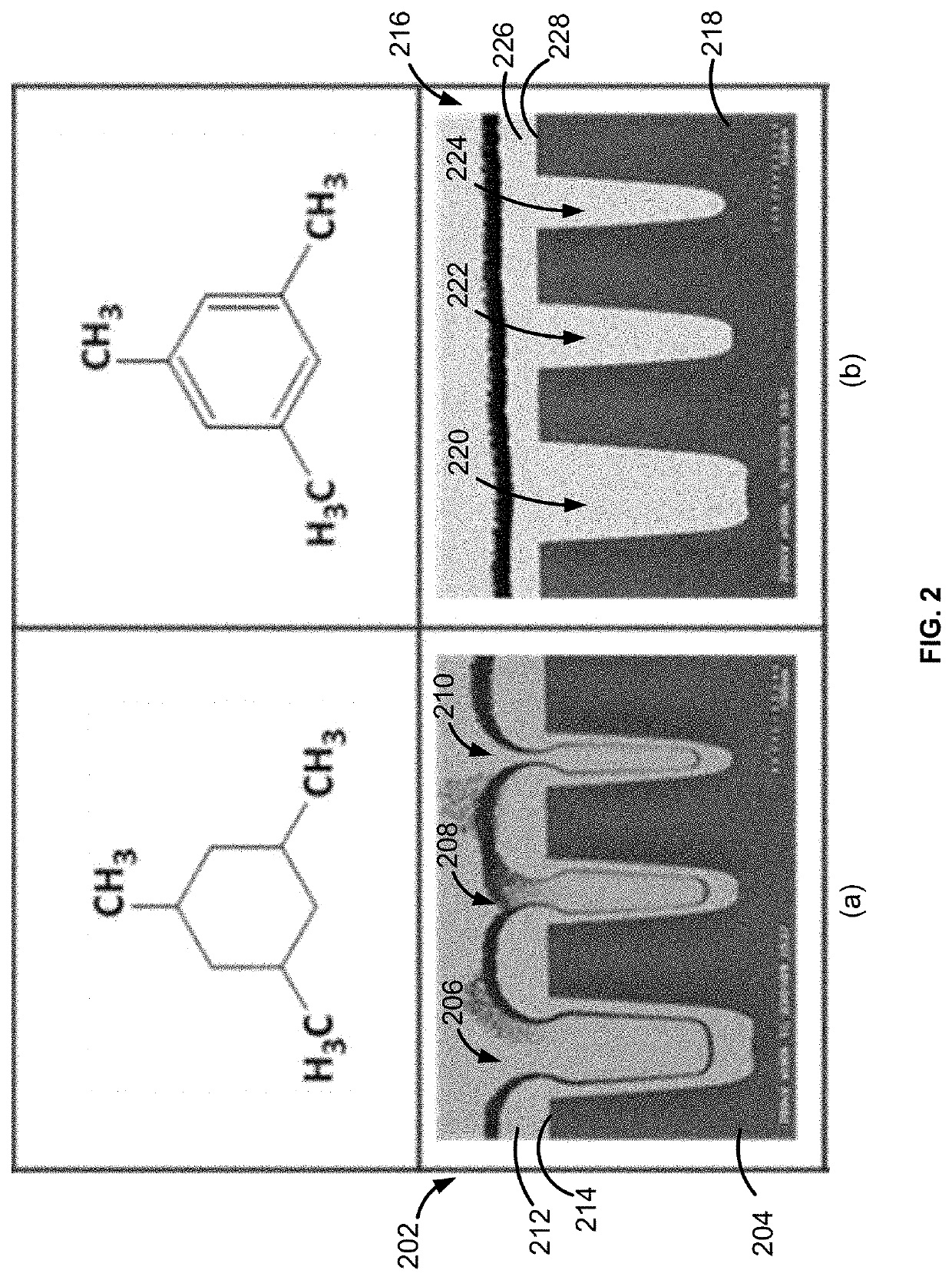
[0024]The present disclosure generally relates to methods of depositing materials, to methods of forming (e.g., film) structures, to film structures formed using the methods, and to systems for performing the methods and / or forming the film structures. By way of examples, the methods described herein can be used to fill features, such as gaps (e.g., trenches or vias) on a surface of a substrate with material, such as carbon (e.g., dielectric) material. The terms gap and recess can be used interchangeably.

[0025]To mitigate void and / or seam formation during a gap-filling process, deposit...


PUM

PropertyMeasurementUnit
Temperatureaaaaaaaaaa
Timeaaaaaaaaaa
Timeaaaaaaaaaa

Abstract

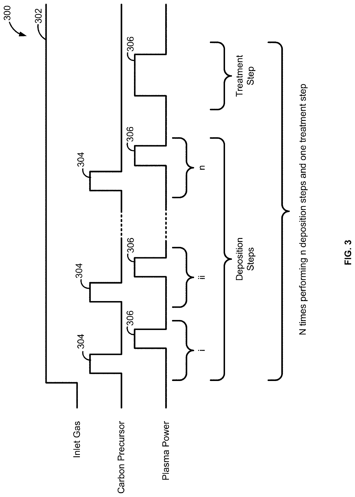
Methods and systems for forming a structure including carbon material and structures formed using the method or system are disclosed. Exemplary methods include providing an inert gas to the reaction chamber for plasma ignition, providing a carbon precursor to the reaction chamber, forming a plasma within the reaction chamber to form an initially viscous carbon material on a surface of the substrate, wherein the initially viscous carbon material becomes carbon material, and treating the carbon material with activated species to form treated carbon material.

Description

CROSS-REFERENCE TO RELATED APPLICATIONS[0001]This application claims the benefit of U.S. Provisional Application No. 62 / 970,483, filed on Feb. 5, 2020, in the United States Patent and Trademark Office, the disclosure of which is incorporated herein in its entirety by reference.FIELD OF INVENTION[0002]The present disclosure generally relates to methods of forming structures suitable for use in the manufacture of electronic devices. More particularly, examples of the disclosure relate to methods of forming structures that include a carbon material layer, to structures including such layers, and to systems for performing the methods and / or forming the structures.BACKGROUND OF THE DISCLOSURE[0003]During the manufacture of devices, such as semiconductor devices, it is often desirable to fill features (e.g., trenches or gaps) on the surface of a substrate with insulating or dielectric material. Some techniques to fill features include the deposition of a layer of flowable carbon material....

Claims


Application Information

Patent Timeline
IPC IPC(8): C23C16/455C23C16/26
CPCC23C16/45538C23C16/26C23C16/0272C23C16/50C23C16/45523C23C16/505C23C16/515C23C16/517C23C16/045H01L21/02115H01L21/02205H01L21/02274H01L21/0234H01L21/0228H01L21/76224C23C16/56
Inventor SUSA, YOSHIOMIYAMA, RYOSUGIURA, HIROTSUGUKIKUCHI, YOSHIYUKI
Owner ASM IP HLDG BV
Learn More