Object identification system and computer-implemented method

a technology of object identification and computer implementation, applied in the field of object identification system and method, can solve the problems of limiting the number of skilled/trained operators in such systems, slowing down security lines, and poor human ability to sporadic visual search

Pending Publication Date: 2021-08-19
NW PRO LTD
View PDF2 Cites 1 Cited by
  • Summary
  • Abstract
  • Description
  • Claims
  • Application Information

AI Technical Summary

Benefits of technology

[0031]In addition to matching of unknown objects to pre-classified objects, embodiments preferably also support guided matching. For example, a user may state an object is a certain model of smartphone and the system may confirm whether there is a match to that model's pre-classified object in the database. Optionally, the system may give a percentage, traffic light style rating (...

Problems solved by technology

It is understood that humans are inherently poor at sporadic visual search of the type described above.
One of the biggest slowdowns in the security lines is caused by an operator manu...

Method used


Image

  • Object identification system and computer-implemented method
  • Object identification system and computer-implemented method
  • Object identification system and computer-implemented method

Examples


Embodiment Construction

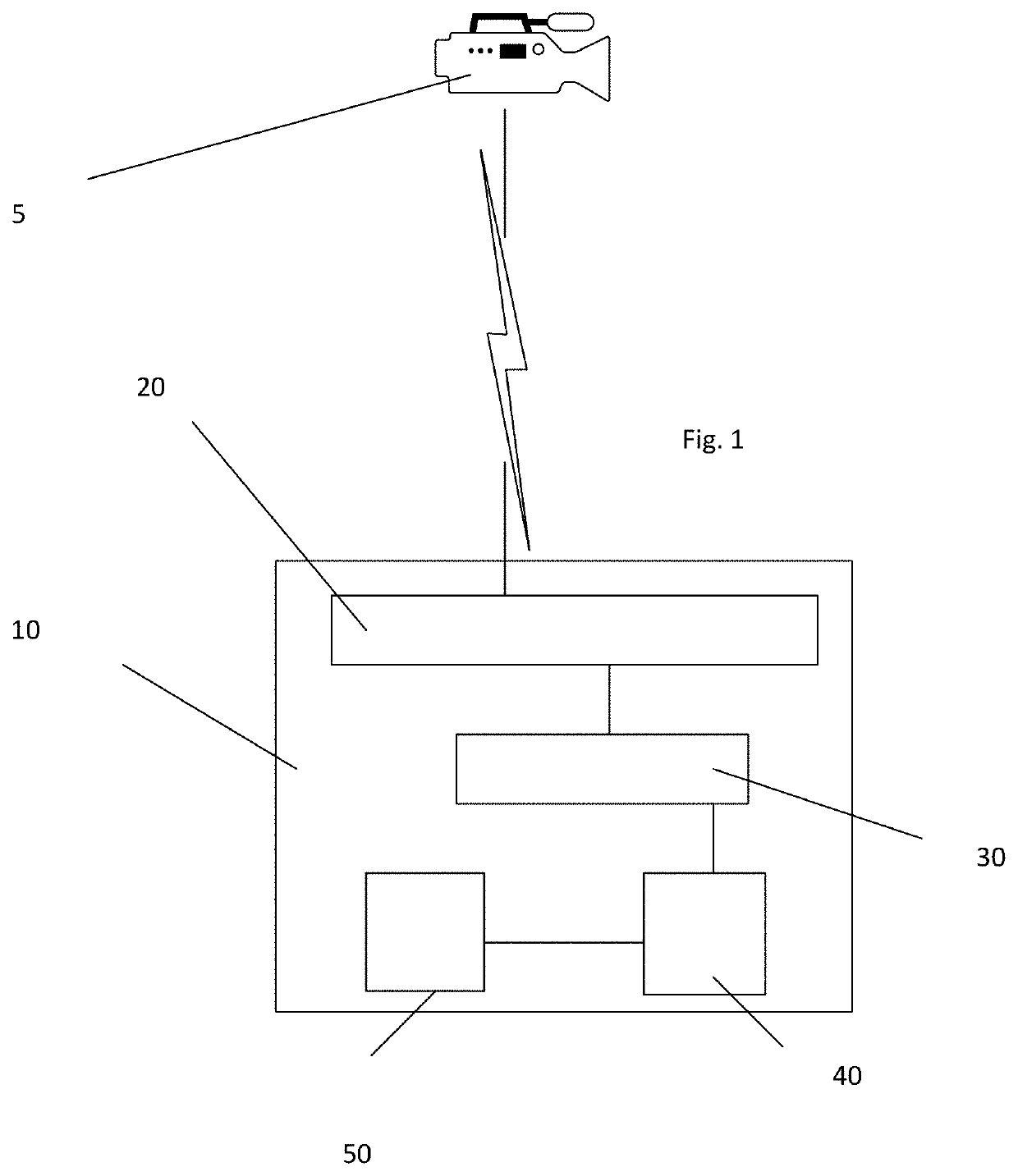
[0041]FIG. 1 is a schematic diagram of an object identification system according to an embodiment.

[0042]The object identification system 10 includes an imaging input interface 20, an imaging processor 30, a classifier 40 and a classification database 50.

[0043]The classification database 50 encodes data on each of a plurality of pre-classified objects

[0044]The imaging input interface 20 is configured to receive imaging data of an object from an imaging scanner such as an X-ray scanner, gamma scanner, a CT scanner or the like. It passes the data to the imaging processor 30 which is configured to process the imaging data to orient and scale it to according to a predetermined grid reference, generating corrected image data.

[0045]The imaging processor 30 acts to ensure that imaging data is normalised and can be matched on a like-for like basis. It may take into account calibration information from the imaging scanner, knowledge of the imaging scanner type, brand etc. It may also consider...


PUM


Abstract

An object identification system and computer implemented method are described. The system includes a classification database encoding data on each of a plurality of pre-classified objects, an imaging input interface configured to receive imaging data of an object from an imaging scanner, the imaging data including imaging data on internal components of the object, an imaging processor configured to receive the imaging data from the imaging input interface and to orient and scale the imaging data according to a predetermined grid reference to generate corrected image data, and a classifier configured to process the corrected image data to segment the image, the classifier being further configured to match the object to one of the pre-classified objects in the classification database in dependence on the segments of the image and on the encoded data in the classification database, the classifier being further configured to identify and output differences between one or more segments of the image and the matched pre-classified object.

Description

CROSS-REFERENCE TO RELATED APPLICATION[0001]This application claims priority to GB Patent Application No. 2002266.1 filed Feb. 19, 2020, the contents of which are incorporated by reference in its entirety as if set forth herein.FIELD OF THE INVENTION[0002]The present invention relates to an object identification system and method that are particularly applicable for identifying malicious modifications to objects.BACKGROUND TO THE INVENTION[0003]In recent years, concern over malicious items smuggled onto planes, into public buildings etc has increased. It is not uncommon for people and their baggage to be scanned prior to entry in an attempt to identify threats such as explosives, blades and the like.[0004]Typically, a machine, such as an x-ray or CT scanner, scans carry-on objects, like a bag, laptop, equipment, or a tray containing various items. Today's standard scanners across most airports use single-view x-ray technology, through which operators see a top-down view of baggage a...

Claims


Application Information

Patent Timeline
IPC IPC(8): G06K9/62G06K9/32G06K9/00G06N3/04G06F16/55G06V10/147G06V10/26G06V10/75G06V10/764
CPCG06K9/627G06K9/3208G06F16/55G06N3/04G06K9/00771G06V20/52G06V10/147G06V10/26G06V10/454G06V10/764G06V10/75G06F18/22G06F18/2413G06F18/2433
Inventor RICHARDS, JAY
Owner NW PRO LTD
Why Eureka
Try Eureka