
Dual door stall correction mechanism

Active Publication Date: 2021-08-26
THE BOEING CO
View PDF0 Cites 0 Cited by
  • Summary
  • Abstract
  • Description
  • Claims
  • Application Information

AI Technical Summary

Benefits of technology

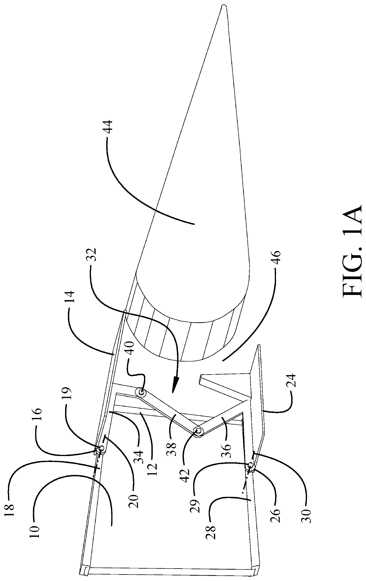
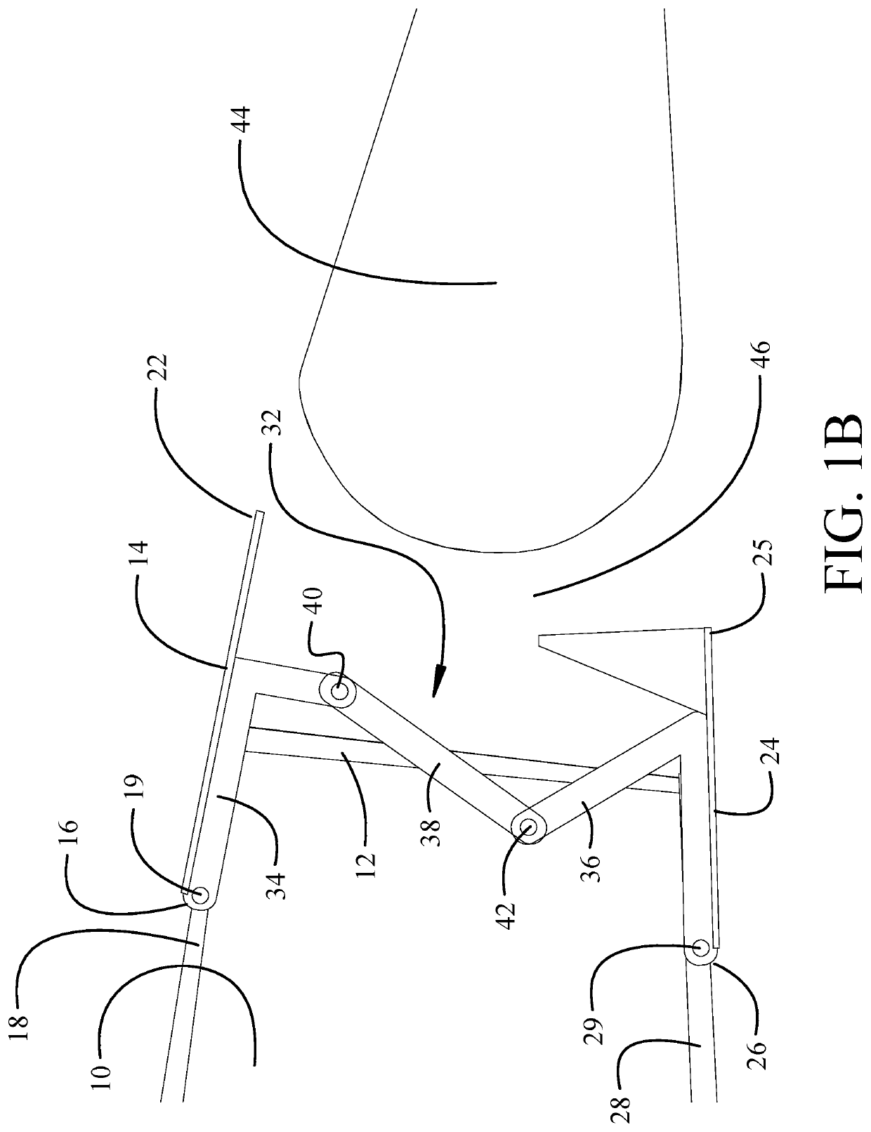
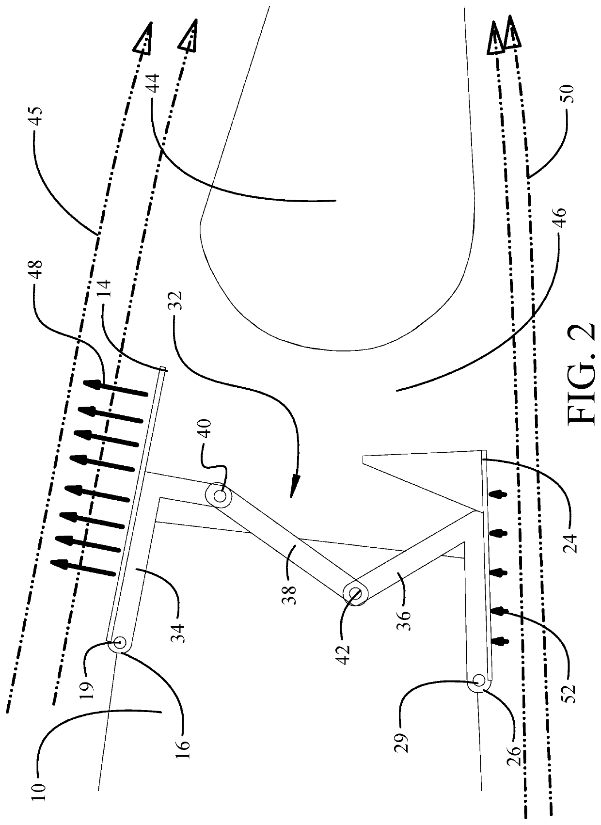
The patent describes a mechanism that helps to prevent a wing from stalling, which can happen when air flows through the wing in an uneven way. The mechanism includes an upper door and a lower door, which can rotate and move in different directions. When the upper door is opened, it causes the lower door to move and create a space that allows air to flow through a flap slot on the wing. This mechanism helps to restore effectiveness and stability to the wing's airflow, preventing stalling and ensuring safe performance.

Problems solved by technology

In high angle of attack orientations, the airflow over the top of the wing incurs separation or turbulence resulting in loss of laminar flow referred to as wing stall.
Loss of laminar air flow on top of the wing surface may causes cause loss of lift or reduced control effectiveness.
This causes some lag in response.

Method used


Image

  • Dual door stall correction mechanism
  • Dual door stall correction mechanism
  • Dual door stall correction mechanism

Examples


Embodiment Construction

[0013]The implementations described herein feature two doors, an upper door pivotally coupled on an upper surface and a lower door pivotally coupled on a lower surface of a wing or wing-like structure. The hinged upper door and lower door are pivotally connected by a coupler During normal flight, laminar flow over the wing provides a pressure profile with a reduced pressure or suction force on the upper surface maintaining a closed position of the upper door and, through the hinged mechanism, a closed position of the lower door. Upon separation or turbulence in the airflow over the upper surface of the wing loss of suction force on the upper surface causes the upper door to rotate inward under gravitational force. The hinged mechanism, in response to the motion of the upper door falling inward pulls the lower door inward as well. Opening of the lower door allows airflow from the lower surface of the wing to divert through a slot opened by the upper and lower doors to the upper surfa...


PUM


Abstract

A wing stall compensation mechanism employs an upper door having forward upper hinge end pivotally coupled to an upper wing structure for rotation about an upper axis and a free aft upper end. A lower door has a free aft lower end and a forward lower hinge end pivotally coupled to a lower wing structure for rotation about a lower axis and a 2-bar coupler linkage is disposed between and pivotally coupled to the upper door and lower door. Downward rotation of the upper door in response to wing surface airflow separation causes contraction of the coupler linkage inducing upward rotation of the lower door from a closed position that inhibits airflow through a flap slot to an open position that enables airflow through the flap slot, to thereby restore wing surface airflow effectiveness.

Description

BACKGROUND INFORMATIONField[0001]This disclosure relates generally to the field of aircraft wing systems and, more particularly to a passive stall correction system having a hinged upper door sensing upper wing flow connected to a lower door, the upper door rotating in response to flow separation and opening the lower door for slotted flow entry.Background[0002]Aircraft wings in flight have a laminar airflow creating a pressure profile over the top of the wing and bottom of the wing. In high angle of attack orientations, the airflow over the top of the wing incurs separation or turbulence resulting in loss of laminar flow referred to as wing stall. Loss of laminar air flow on top of the wing surface may causes cause loss of lift or reduced control effectiveness. Various mechanisms have been employed to provide stall correction or prevention. Flap systems including both plain and slotted flaps allow aircraft operation at higher angles of attack by preventing early flow separation the...

Claims


Application Information

Patent Timeline
IPC IPC(8): B64C13/30B64C9/18B64C21/06
CPCB64C13/30B64C21/06B64C9/18B64C21/025Y02T50/10
Inventor PETERSON, MIRANDATSAI, KEVIN R.
Owner THE BOEING CO
Learn More