
Oil filter

a technology of oil filter and oil filter body, which is applied in the direction of moving filter element filter, filtration separation, and separation process, can solve the problems of engine wear and eventual damage, much sooner engine damage than, and particulate matter, and achieve the effect of restoring the effectiveness of the primary filter and easy cleaning

Active Publication Date: 2010-09-23
HUBB FILTERS
View PDF26 Cites 9 Cited by
  • Summary
  • Abstract
  • Description
  • Claims
  • Application Information

AI Technical Summary

Benefits of technology

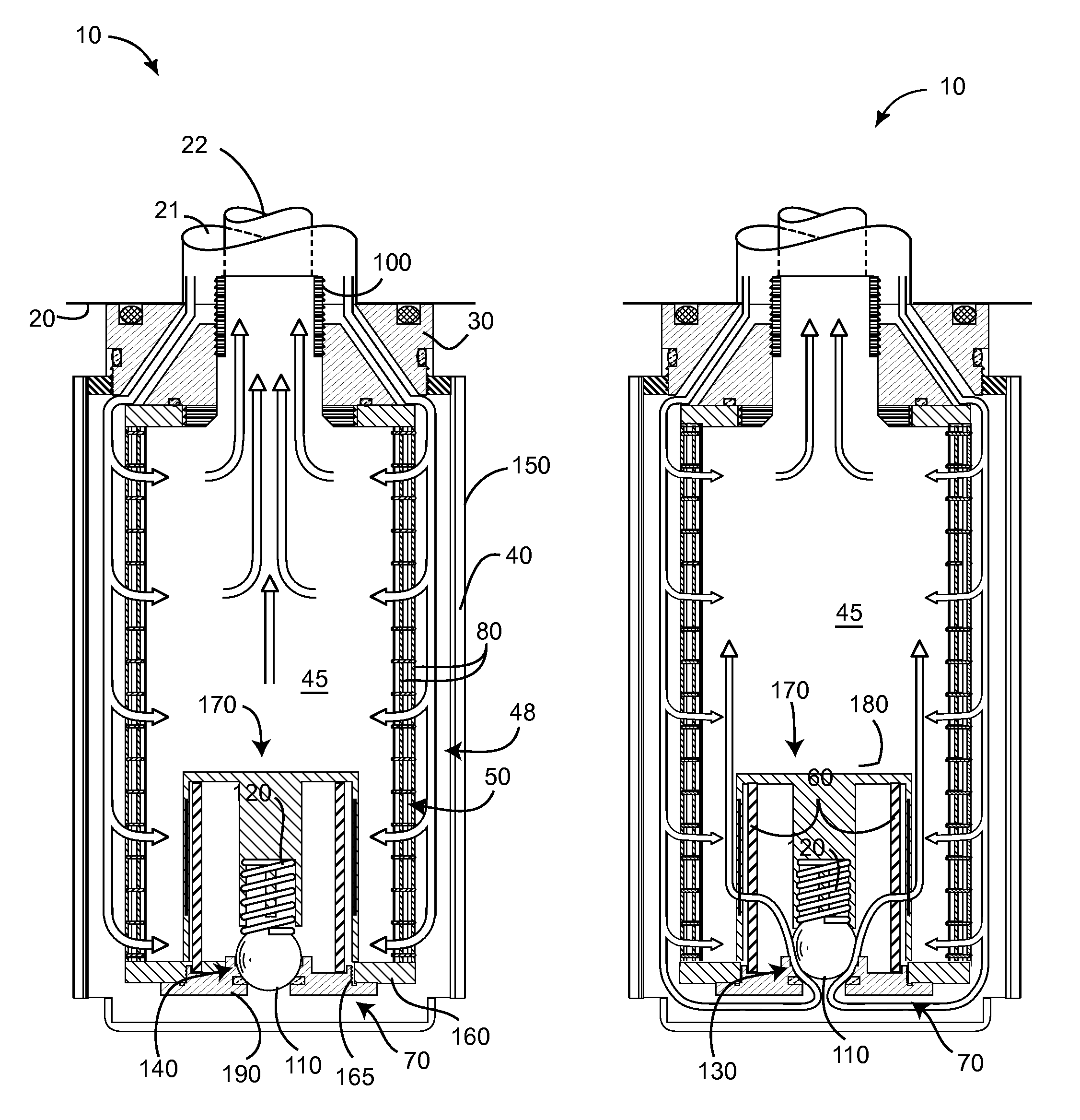
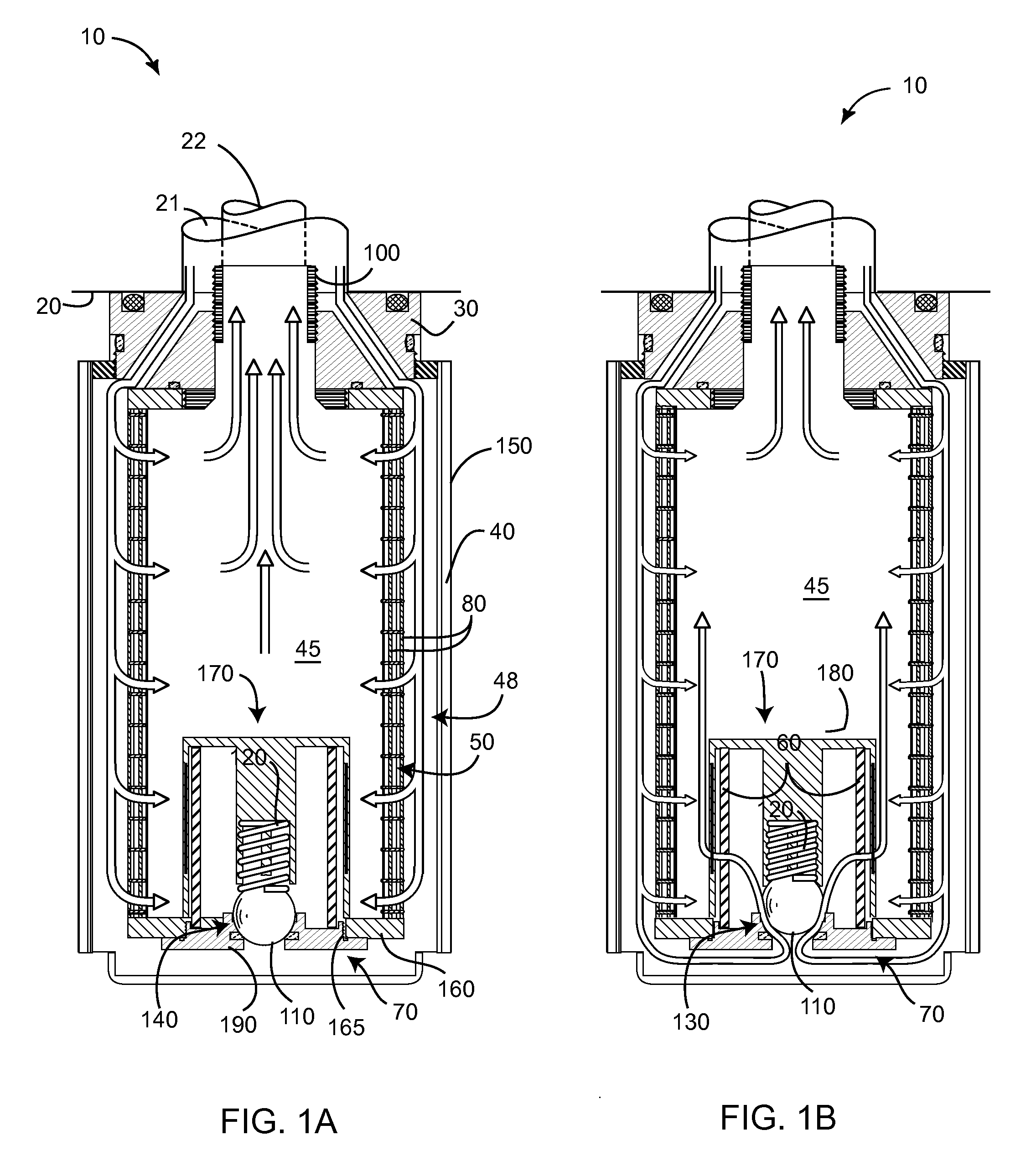
[0011]The present invention is a filter device that opens the bypass pressure-actuated valve once the primary filter becomes plugged, but additionally continues to filter the oil through the secondary more porous filter. The present device is easily cleaned, such as in a conventional household dishwasher, to restore the effectiveness of the primary filter, and is made of durable materials that can last potentially longer than the vehicle or machine to which it is installed. The present invention further cools the oil as it passes therethrough. Other features and advantages of the present invention will become apparent from the following more detailed description, taken in conjunction with the accompanying drawings, which illustrate, by way of example, the principles of the invention.

Problems solved by technology

One drawback with such devices is that once the bypass valve is opened, particulate debris that would normally be captured by the filter media is able to traverse the valve and re-enter the engine, leading to engine wear and eventual damage.
However, forcing oil through a filter media has the drawback that once the filter media becomes plugged with particulate matter, not enough oil can get through the filter to effectively cool the engine, leading to much sooner engine damage than if even dirty oil were allowed to circulate.
Another drawback of such devices is that particulate matter, once captured on a leading side of the filter media, can be dislodged from the filter to return back to the engine once the bypass valve opens, since flow of the oil at that point changes from through the filter media to across the filter media.
These devices suffer many of the same drawbacks as the Faria device.

Method used


Image

  • Oil filter
  • Oil filter
  • Oil filter

Examples


Embodiment Construction

[0022]Illustrative embodiments of the invention are described below. The following explanation provides specific details for a thorough understanding of and enabling description for these embodiments. One skilled in the art will understand that the invention may be practiced without such details. In other instances, well-known structures and functions have not been shown or described in detail to avoid unnecessarily obscuring the description of the embodiments.

[0023]Unless the context clearly requires otherwise, throughout the description and the claims, the words “comprise,”“comprising,” and the like are to be construed in an inclusive sense as opposed to an exclusive or exhaustive sense; that is to say, in the sense of “including, but not limited to.” Words using the singular or plural number also include the plural or singular number respectively. Additionally, the words “herein,”“above,”“below” and words of similar import, when used in this application, shall refer to this appli...


PUM

PropertyMeasurementUnit
porosityaaaaaaaaaa
pressureaaaaaaaaaa
pressure thresholdaaaaaaaaaa

Abstract

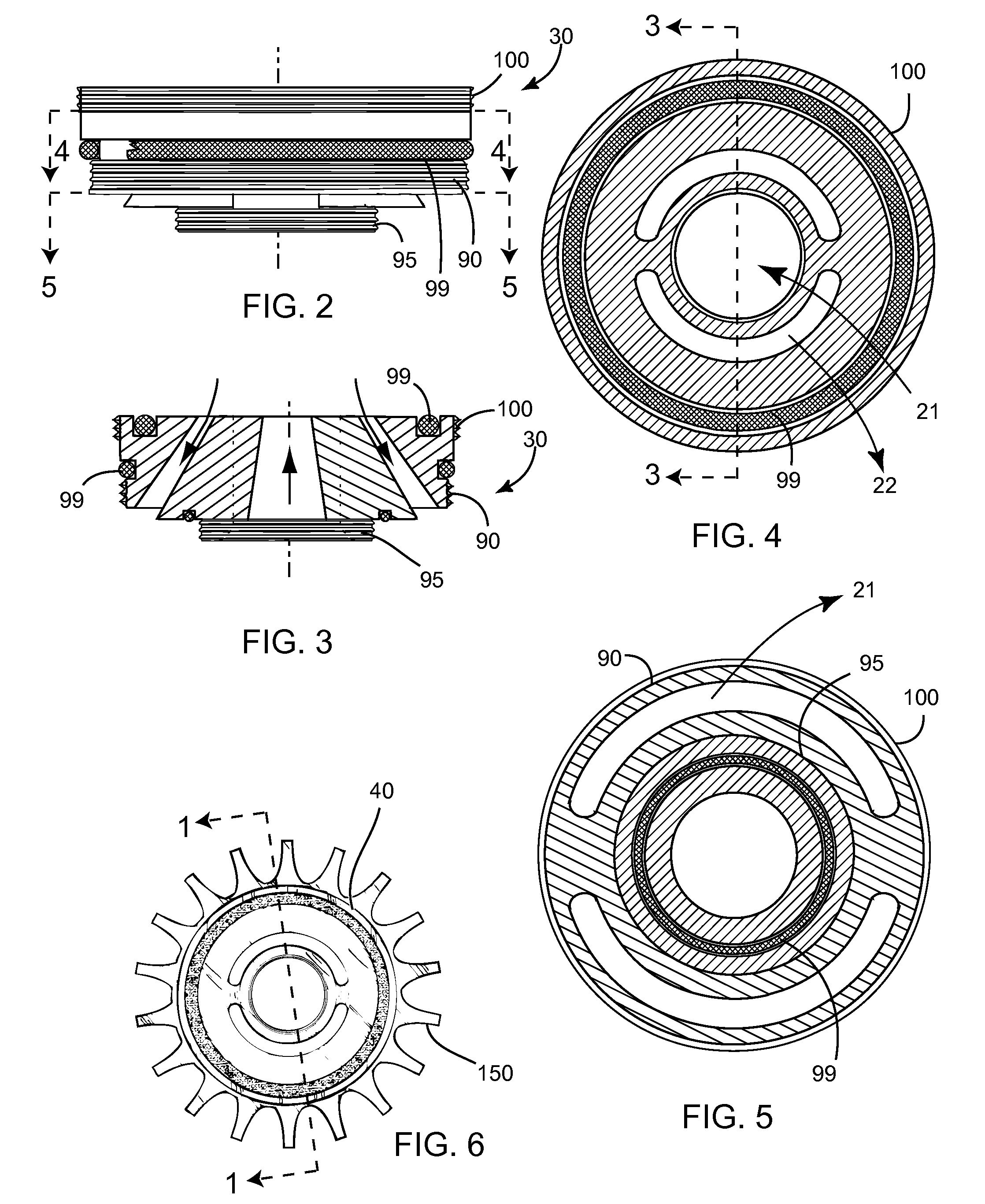
An oil filter assembly is disclosed for a machine, such as an internal combustion engine, that has an oil output port and an oil input port. A mounting plate is fixed with an outer enclosure and is adapted for securing to the machine. The mounting plate is further adapted to conduct oil from the machine into a peripheral portion of the outer enclosure, and then returning oil from a central portion of the outer enclosure back to the machine. Oil may pass from the peripheral portion to the central portion through a primary filter having a first porosity. A pressure-actuated valve is fixed fluidly between the peripheral portion and central portion of the outer enclosure. Oil may pass through the pressure-actuated valve only when an oil pressure differential between the peripheral portion and the central portion of the outer enclosure exceeds a predetermined threshold pressure. A secondary filter has a second porosity greater than the first porosity, and is fixed fluidly between the pressure-actuated valve and the central portion of the outer enclosure.

Description

CROSS-REFERENCE TO RELATED APPLICATIONS[0001]Not Applicable.STATEMENT REGARDING FEDERALLY SPONSORED RESEARCH AND DEVELOPMENT[0002]Not Applicable.NOTICE OF COPYRIGHTS AND TRADE DRESS[0003]A portion of the disclosure of this patent document contains material which is subject to copyright protection. This patent document may show and / or describe matter which is or may become trade dress of the owner. The copyright and trade dress owner has no objection to the facsimile reproduction by any one of the patent disclosure as it appears in the Patent and Trademark Office patent files or records, but otherwise reserves all copyright and trade dress rights whatsoever.FIELD OF THE INVENTION[0004]This invention relates to filters, and more particularly to an improved engine oil filter assembly.DISCUSSION OF RELATED ART[0005]Conventional oil filters for vehicle engines, such as automotive internal combustion engines, typically include a filter media and a bypass valve that is actuated when the fi...

Claims


Application Information

Patent Timeline
Patent Type & Authority Applications(United States)
IPC IPC(8): B01D29/54B01D29/60
CPCB01D29/114B01D35/147B01D2201/304B01D27/103Y10S210/17Y10S210/13B01D35/005B01D27/144B01D29/0022B01D29/54B01D29/117B01D29/21B01D29/232B01D29/016B01D35/1475
Inventor HUBBARD, CHRISTOPHER
Owner HUBB FILTERS
Learn More