Engine-mounting links that have an adjustable inclination angle

a technology of inclination angle and engine, which is applied in the direction of power plant arrangement/mounting, power plant construction, aircraft power plants, etc., can solve the problems of certain amount of deflection or bending of the engine, and achieve the effect of reducing specific fuel consumption

Pending Publication Date: 2021-08-26
GENERAL ELECTRIC CO
View PDF5 Cites 0 Cited by
  • Summary
  • Abstract
  • Description
  • Claims
  • Application Information

AI Technical Summary

Benefits of technology

[0012]In yet another aspect, the present disclosure embraces method of operating an aircraft, such as methods of chaining an inclination angle θ, methods of reducing specific fuel consumption, and so forth. An exemplary method may include receiving an input from a sensor, and / or outputting a control command responsive to the input from the sensor. The control command may be operable to actuate an actuator that, when actuated, causes a change to an inclination angle θ of at least one of a plurality of engine-mounting links that connect an engine frame of an aircraft engine to an engine support structure that defines a location for mounting the aircraft engine to an aircraft. The plurality of engine-mounting links may include a forward link that is connected to a forward frame portion of the engine frame and the engine support structure, and / or an aft link that is connected to an aft frame portion of the engine frame and the engine support structure. The actuator may be connected to the engine support structure and one of and the plurality of engine-mounting links, or to the engine support structure and the engine frame.
[0013]In yet another aspect, a method of controlling a link operably coupling an engine with an engine support structure is provided. The method includes determining a control command based at least in part on an output received from one or more sensors. Further, the method includes causing an actuator operably coupled with the link to change a position of the link based at least in part on the determined control command.
[0014]In a further aspect, a control system for controlling a link configured to operably couple an engine to an engine mounting structure of a vehicle is provided. The control system includes one or more sensors and an actuator operably couplable with the link. The actuator is operable to change an inclination angle of the link. Further, the control system includes one or more controllers communicatively coupled with the one or more sensors and the actuator. The one or more controllers having one or more memory devices and one or more processing devices, the one or more memory devices storing computer-readable instructions that can be executed by the one or more processing devices to perform operations, in performing the operations, the one or more processing devices are configured to: determine a control command based at least in part on an output received from the one or more sensors; and cause the actuator to change the inclination angle of the link based at least in part on the determined control command.
[0015]In another aspect, a computer readable medium is provided. The computer readable medium includes computer-executable instructions, which, when executed by one or more processors of an engine controller, cause the engine controller to: cause an actuator operably couplable with a link configured to operably couple an engine with an engine mounting structure to vary an inclination angle of the link to a plurality of preselected inclination angles; receive, for respective ones of the plurality of preselected inclination angles, a value for one or more operating parameters associated the respective ones of the plurality of preselected inclination angles; generate a dataset relating the plurality of preselected inclination angles to the values for the one or more operating parameters, the received values depending at least in part on the inclination angle associated therewith; and select the inclination angle based at least in part on the dataset, the selected inclination angle corresponding to a value for one of the one or more operating parameters. The computer readable medium can be a non-transitory computer-readable medium, for example.
[0016]In another aspect, a method of controlling a link angle of a link operatively coupling an engine with a mounting structure is provided. The method includes determining a control command based at least in part on one or more operating parameters received from one or more sensors, the control command indicative of instructions for varying the link angle of the link. Further, the method includes providing the control command to an actuator operable to vary the link angle based at least in part on the determined control command.

Problems solved by technology

These various loads may cause a certain amount of deflection or bending of the engine.

Method used


Image

  • Engine-mounting links that have an adjustable inclination angle
  • Engine-mounting links that have an adjustable inclination angle
  • Engine-mounting links that have an adjustable inclination angle

Examples


Embodiment Construction

[0038]Reference now will be made in detail to exemplary embodiments of the presently disclosed subject matter, one or more examples of which are illustrated in the drawings. Each example is provided by way of explanation and should not be interpreted as limiting the present disclosure. In fact, it will be apparent to those skilled in the art that various modifications and variations can be made in the present disclosure without departing from the scope of the present disclosure. For instance, features illustrated or described as part of one embodiment can be used with another embodiment to yield a still further embodiment. Thus, it is intended that the present disclosure covers such modifications and variations as come within the scope of the appended claims and their equivalents.

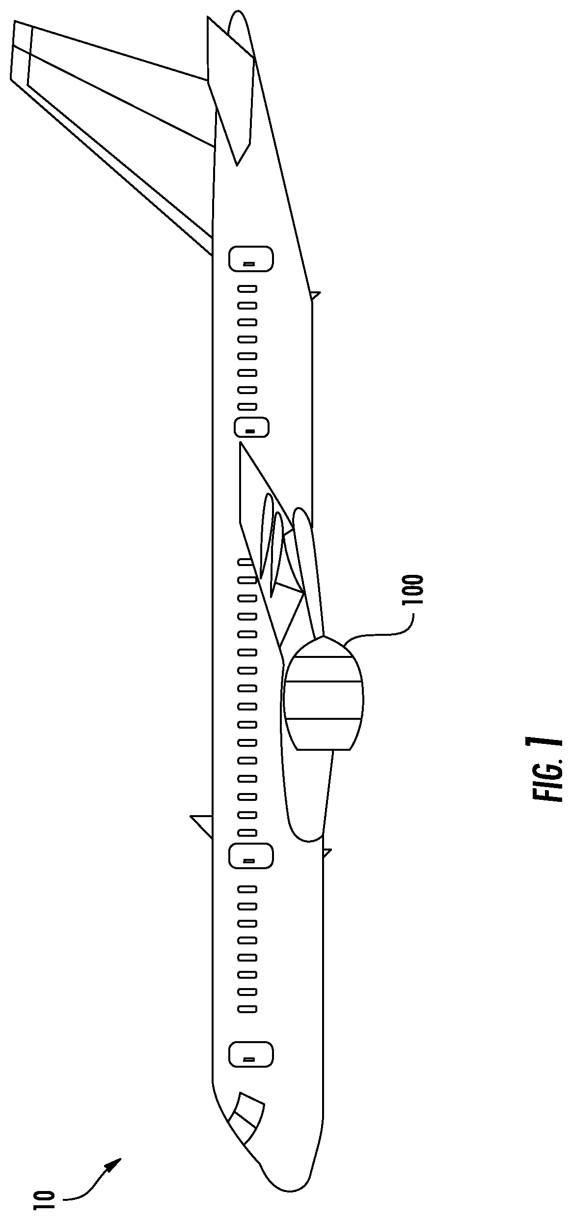
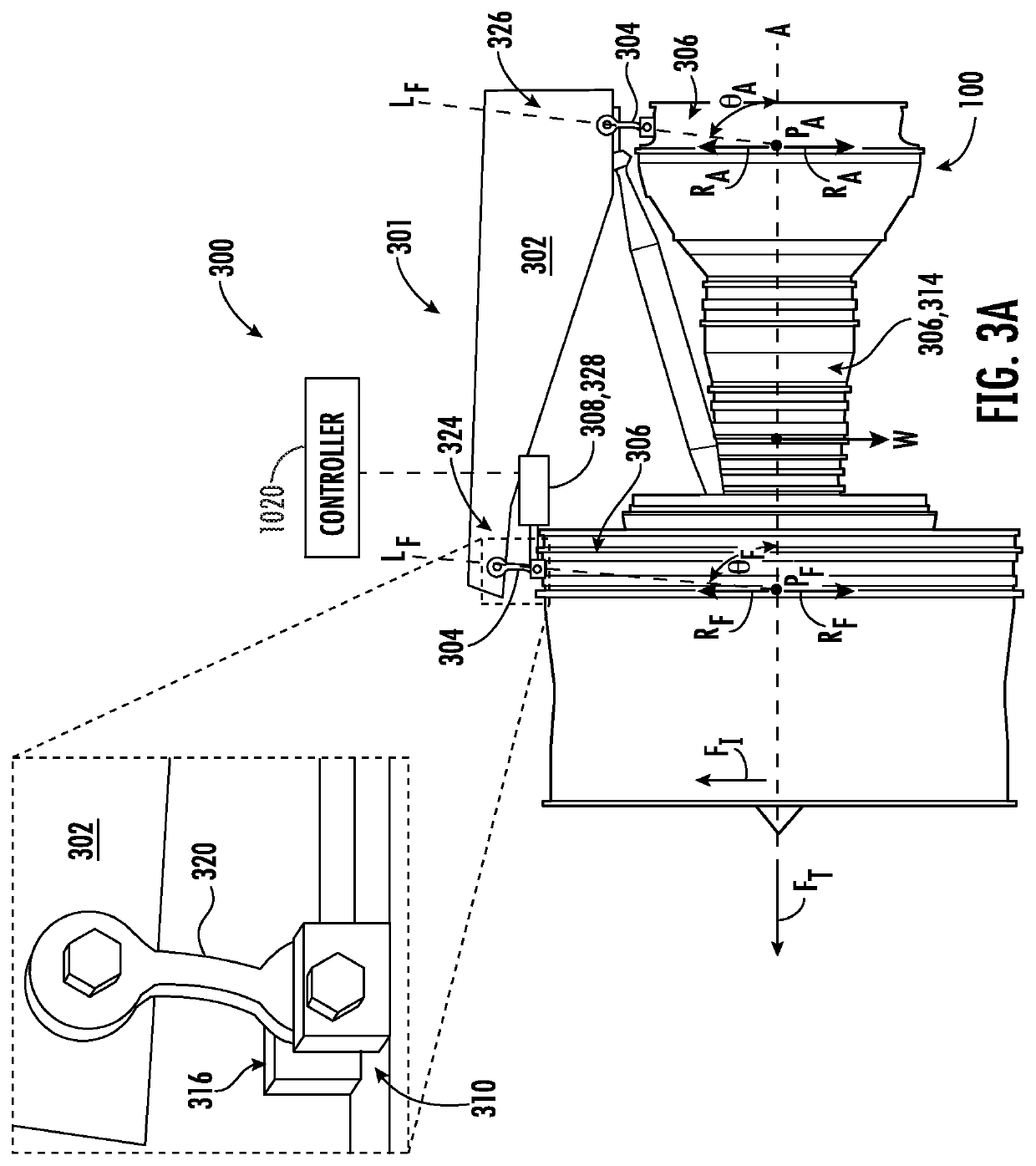
[0039]The present disclosure generally provides engine-mounting linkage systems for mounting an aircraft engine to an engine support structure of an aircraft. The presently disclosed engine-mounting linkage...


PUM


Abstract

Engine-mounting linkage systems may include a plurality of engine mounting links configured to couple an engine frame to an engine support structure of an aircraft. The plurality of engine-mounting links may include a forward link that is connectable to a forward frame portion of the engine frame and the engine support structure, and an aft link that is connectable to an aft frame portion of the engine frame and the engine support structure. The engine mounting linkage system may include an actuator that is connectable to the engine support structure and one of the plurality of engine-mounting links, or to the engine support structure and the engine frame. The actuator, when actuated, changes an inclination angle θ of at least one of the plurality of engine-mounting links.

Description

FIELD[0001]The present disclosure generally pertains to systems and methods for mounting an aircraft engine to an aircraft. More particularly, the present disclosure pertains systems and methods that utilize engine-mounting links that have an adjustable inclination angle.BACKGROUND[0002]Aircraft engines such as turbomachines may be mounted to an aircraft at various locations such as the wings, fuselage, or tail. Aircraft engines include gas turbine powered engines, electric engines, hybrid engines, and piston engines. The engine is typically mounted at axially spaced apart forward and aft or front and rear positions by an engine support structure that includes corresponding forward and aft or front and rear mounts for carrying various loads to the aircraft. The loads typically include vertical loads such as the weight of the engine itself, axial thrust loads generated by the engine, lateral loads such as those due to wind buffeting, and roll loads or moments due to rotary operation ...

Claims


Application Information

Patent Timeline
Patent Type & Authority Applications(United States)
IPC IPC(8): B64D27/26
CPCB64D27/26B64D2027/268B64D2027/266
Inventor SCHELFAUT, TIMOTHY LEOMETZ, ANTHONY MICHAELCOLEMAN, JONATHAN EDWARDJOSEPH, THOMAS P.BORNER, MICHAEL C.KHANDEPARKER, MAHESHSHINDE, KUDUM
Owner GENERAL ELECTRIC CO
Why Eureka
Try Eureka