Control method for intake and exhaust management system of supercharged engine
A supercharged engine and engine controller technology, applied in engine control, electrical control, engine components, etc., can solve the problems of low compressor outlet pressure, small application range, poor acceleration response of the whole vehicle, etc., to reduce design costs and The effect of production cost, production cost reduction, and design cost reduction
- Summary
- Abstract
- Description
- Claims
- Application Information
AI Technical Summary
Problems solved by technology
Method used
Image
Examples
Embodiment 1
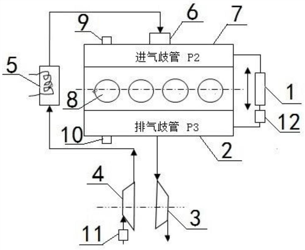
[0065] A control method for a supercharged engine intake and exhaust management system, the control method is based on the following structure:
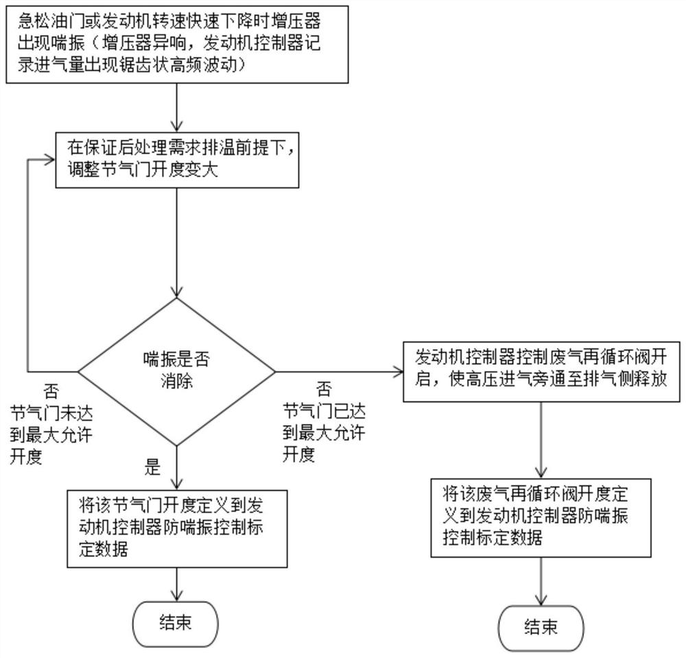
[0066] The engine intake and exhaust management system includes: two-way bypass valve 1, exhaust manifold 2, turbine 3, compressor 4, intercooler 5, throttle valve 6, intake manifold 7, cylinder 8, intake pressure sensor 9, exhaust pressure sensor 10 and air flow sensor 11; the intake end of the cylinder 8 is provided with an intake manifold 7, the outlet end of the cylinder 8 is provided with an exhaust manifold 2, and the two-way bypass One end of the valve 1 communicates with the exhaust manifold 2, the other end of the two-way bypass valve 1 communicates with the intake manifold 7, and the outlet end of the exhaust manifold 2 is provided with a turbine 3, the turbine The outlet end of 3 is connected to the atmosphere through the exhaust pipeline and after-treatment system, the turbine 3 is coaxial with the compressor 4, the inlet...
Embodiment 2
[0080] Embodiment 2 is basically the same as Embodiment 1, and its difference is:
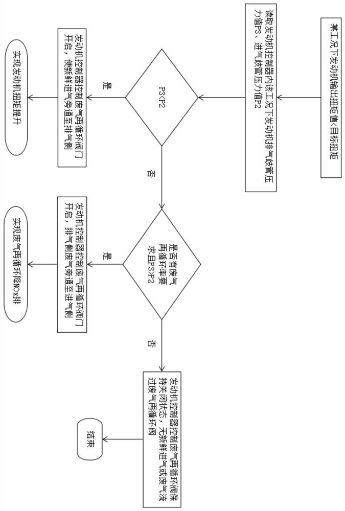
[0081] In the first step of data collection, the engine controller detects that the intake manifold pressure P2 of the engine under the full load condition of 1000rpm is 98kpa, and the exhaust manifold pressure P3 is 92kpa;
[0082] The second step is to determine the working mode. In the step, the engine controller detects that the air flow value P1 collected by the air flow sensor 11 does not have sawtooth fluctuations. At the same time, the intake manifold pressure value of 98kpa is greater than the exhaust manifold pressure value of 92kpa. The two-way bypass valve 1 Enter the fourth step torque boost mode;
[0083] In the fourth step of torque boost mode, the engine controller sends a control signal to drive the two-way bypass valve 1 to open until the opening reaches 5%. After the two-way bypass valve 1 starts to work, it is connected to the engine intake manifold 7 and exhaust manifold 2 ...
Embodiment 3
[0085] Embodiment 3 is basically the same as Embodiment 2, and its difference is:
[0086] In the fourth step of the torque boost mode, the engine controller sends a control signal to drive the two-way bypass valve 1 to open until the opening reaches 10%, and the torque can be increased to 385N when the fuel injection volume remains unchanged at 9.3kg / h .m.
PUM
 Abstract
Description
Claims
Application Information
 - R&D
- Intellectual Property
- Life Sciences
- Materials
- Tech Scout
- Unparalleled Data Quality
- Higher Quality Content
- 60% Fewer Hallucinations
Browse by: Latest US Patents, China's latest patents, Technical Efficacy Thesaurus, Application Domain, Technology Topic, Popular Technical Reports.
© 2025 PatSnap. All rights reserved.Legal|Privacy policy|Modern Slavery Act Transparency Statement|Sitemap|About US| Contact US: help@patsnap.com


