Multi-Stage Nasal Filter

a filtration device and multi-stage technology, applied in the direction of filtration separation, separation process, transportation and packaging, etc., can solve the problems of insufficient state of the art response protocol, inconvenient intranasal use of high-impedance materials used in face masks, and less effective devices against the smaller particle sizes, etc., to achieve reduced effective impedance, reduce the effect of intrinsic impedance, and large cross-sectional area

Active Publication Date: 2021-09-02
STROBL FREDERICK THOMAS
View PDF0 Cites 0 Cited by
  • Summary
  • Abstract
  • Description
  • Claims
  • Application Information

AI Technical Summary

Benefits of technology

[0012]Various embodiments of the present invention involve using a filter material having a relatively high intrinsic impedance to construct an intra-nasal filter stage, by configuring the filter material to present a large cross-sectional area and thereby reduce its effective impedance. In this way, relatively higher impedance materials may be employed without causing user discomfort or distress.

Problems solved by technology

Recent outbreaks of infectious disease have proven state of the art response protocols to be wholly inadequate, including efforts at containment, quarantine, information dissemination, vaccine development, and travel restrictions.
However, these devices are less effective against the smaller particle sizes which characterize the Coronavirus and other strains of influenza (e.g., 0.1-0.3 microns).
Longstanding and accepted design practices therefore recognize that the high impedance materials used in face masks are not well suited for intranasal use.
However, drawing the same volume of air through a conventional nasal filter having a surface area in the range of 0.25 in2 would be uncomfortable if not physically impossible for most people.
Consequently, very small particle sizes in the 0.1-0.3 micron range pass through such intra-nasal filters and enter the body, potentially causing infection.

Method used


Image

  • Multi-Stage Nasal Filter
  • Multi-Stage Nasal Filter
  • Multi-Stage Nasal Filter

Examples


first embodiment

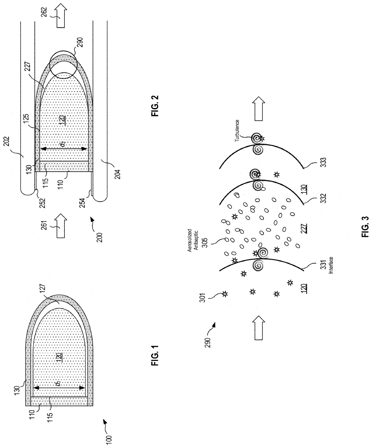
[0063]Referring now to FIG. 1, a multi-stage nasal filter assembly 100 comprises all or a subset of a first stage filter 110, a second stage filter 120, and a third stage filter 130. The first stage filter no may comprise a disc shaped structure supporting a first filter layer characterized by one or more MPPS values. The second stage filter 120 may partially or wholly comprise a semi rigid or resiliently deformable material such as plastic or nylon.

[0064]The second stage filter may also include one or more sub-layers embedded into, circumscribing, or otherwise adjacent to the internal and / or external boundary surfaces of element 120. In addition, one or more of the filter layers may be convoluted; that is, the material may be folded, pleated, or otherwise configured to expand the effective surface area of the material in three dimensions as described in greater detail below in conjunction with FIG. 8.

[0065]In this way the second stage may expand when inserted to form a gentle seal ...

embodiment 900

[0078]FIG. 9 illustrates an alternate embodiment 900 of the multi-stage filter of FIG. 8, wherein the second stage 920 comprises a “solid” interior terminating in a plurality of convex convolutions 925, resulting in a substantial gap 927 between the ends of the convolutions and the inside surface of the third stage filter layer 930. A resiliently expandable ring 910 may be used to help urge the second (and possibly the first) stage material outwardly against the adjacent nasal wall to form a perimeter seal. The optional ring 910 may be integral to the first stage filter structure, circumscribe the first stage structure, or partially or entirely replace the first stage.

[0079]FIG. 10A is a schematic cross-section view of an alternate embodiment 901 of a multi-stage filter similar to FIG. 8 or 9, including an optional, resiliently expandable claw disposed with its convex region extending in the distal direction of the nasal passage. The claw performs a function similar to that performe...

embodiment 1300

[0097]FIG. 12D illustrates an alternate embodiment 1300 in which the material 1310 is configured as a surface-of-revolution of sinusoidal curve around the longitudinal axis. That is, the illustrated curve has the form:

surface of revolution: y=−kx+d+l sin(nx),

[0098]where k, d, and l are constants. It has been found that structures with this form also provide some of the benefits of the above embodiment—i.e., material with a relatively large surface area can be enclosed within a relatively small nasal cavity volume.

[0099]Those skilled in the art will appreciate that the foregoing geometric configurations are merely exemplary, and that the present invention contemplates virtually any geometric, topological, and / or other spatial manipulation of the filter material which increases the surface area and thereby reduces the impedance of the filter material.

[0100]Additional embodiments may contemplate a filter wherein a particular stage itself comprises two “stages,” wherein the airflow is f...


PUM

PropertyMeasurementUnit
areaaaaaaaaaaa
particle sizeaaaaaaaaaa
cross-sectional areaaaaaaaaaaa

Abstract

Intra-nasal filter devices and methods for their manufacture and use are disclosed. An intra-nasal filter device includes: a first stage filter proximate the septum; and a second stage filter comprising a flexible material extending upwardly from the first filter stage filter; wherein the flexible material comprises: an impedance in the range of 0.02 to 0.2 cmH2O; an effective cross-sectional area in the range of 0.2 to 2 square inches; and a plurality of radially extending geometric structures disposed along an axial length of the second stage.

Description

REFERENCE TO RELATED APPLICATIONS[0001]This non-provisional patent application is a continuation-in-part application of U.S. patent application Ser. No. 16 / 806,857 filed Mar. 2, 2020, the entire contents of which is hereby incorporated by this reference.TECHNICAL FIELD[0002]The present disclosure generally relates to a multi-stage filtration device insertable into human nostrils for filtering allergens and pathogens from an inhaled ambient air stream and, more particularly, to a filter material exhibiting a three dimensional topology designed to increase surface area and reduce air flow impedance.BACKGROUND OF THE DISCLOSURE[0003]Recent outbreaks of infectious disease have proven state of the art response protocols to be wholly inadequate, including efforts at containment, quarantine, information dissemination, vaccine development, and travel restrictions. Influenza epidemics such as SARS (Severe Acute Respiratory Syndrome) in 2003, H1N1 in 2011, avian in 2015, and the Coronavirus o...

Claims


Application Information

Patent Timeline
Patent Type & Authority Applications(United States)
IPC IPC(8): A62B23/06B01D39/16B01D36/00
CPCA62B23/06B01D39/1692B01D36/001B01D2239/025B01D2201/088B01D2239/1216B01D2239/0442B01D2201/02B01D2201/12B01D2239/0631B01D2239/0435B01D2239/125B01D2239/1233B01D2239/065B01D2239/0668B01D2239/0677B01D2239/0681B01D39/1676B01D39/1669B01D39/1623B01D39/1615B01D39/08B01D2239/0471B01D2239/0464B01D46/103B01D46/64
Inventor STROBL, FREDERICK THOMAS
Owner STROBL FREDERICK THOMAS
Why Eureka
Try Eureka