Hinged temperature-immune self-referencing Fabry-Pérot cavity sensors

Active Publication Date: 2021-09-02
THE UNITED STATES OF AMERICA AS REPRESETNED BY THE SEC OF THE AIR FORCE
View PDF0 Cites 0 Cited by
  • Summary
  • Abstract
  • Description
  • Claims
  • Application Information

AI Technical Summary

Benefits of technology

This patent is about an invention made by U.S. government employees and can be used without paying royalties by the U.S. government. The technical effect of this patent is that it allows the U.S. government to manufacture and use the invention for government purposes without needing to pay any royalties on it.

Problems solved by technology

[3] While often beneficial, the open nature of the FP cavity means it lacks lateral confinement, and loses some resonant light off the edges of the mirrors.
Flat FP cavities are highly sensitive to misalignment, and any misalignment, even one of several degrees, between the mirrors will significantly lower a cavity's quality factor.
[1] One popular way to overcome this sensitivity is by using one or more curved mirrors, [3-5] although this often increases the complexity of fabrication.
Poor lateral confinement and misalignment sensitivity continue to plague fiber based FP cavity devices, and represent significant design challenges.
The fiber itself is also an exotic substrate due to its geometry, which renders it incompatible with many planar microfabrication processes.
[24] While this design can interrogate gasses, liquids would have difficulty reaching the cavity through the small openings in the PFC.
Splicing various types of optical fibers also requires precise alignment and may be difficult to repeat reliably.
[22] While the environment is easily accessed by this cavity, the fabrication process is complex and laborious, involving CO2 laser pulling and metal deposition before the ion milling.
But this process is also relatively complicated, requiring a spray coat, bake, and UV exposure for each individual layer.
This also limits the 3-D structures that can be realistically built.

Method used


Image

  • Hinged temperature-immune self-referencing Fabry-Pérot cavity sensors
  • Hinged temperature-immune self-referencing Fabry-Pérot cavity sensors
  • Hinged temperature-immune self-referencing Fabry-Pérot cavity sensors

Examples


Embodiment Construction

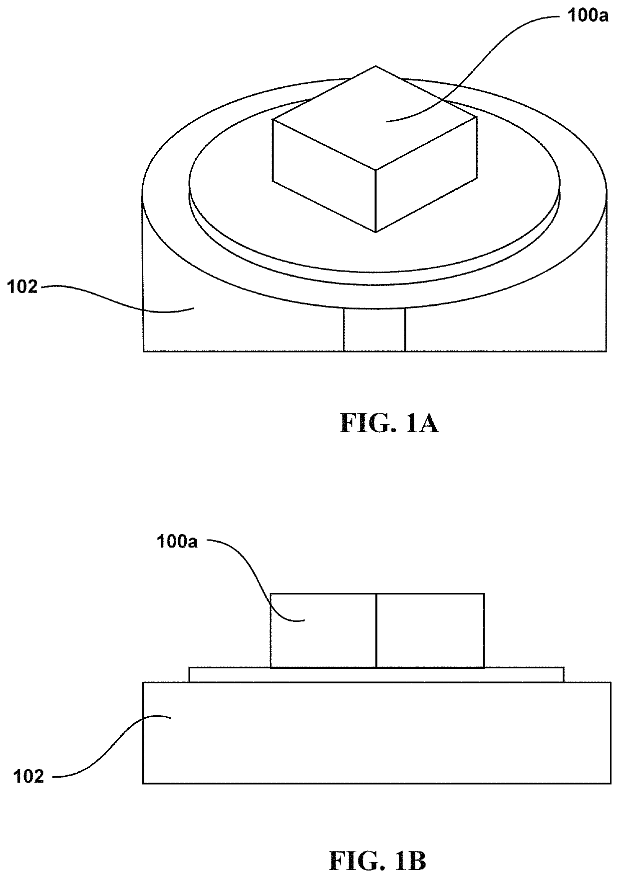
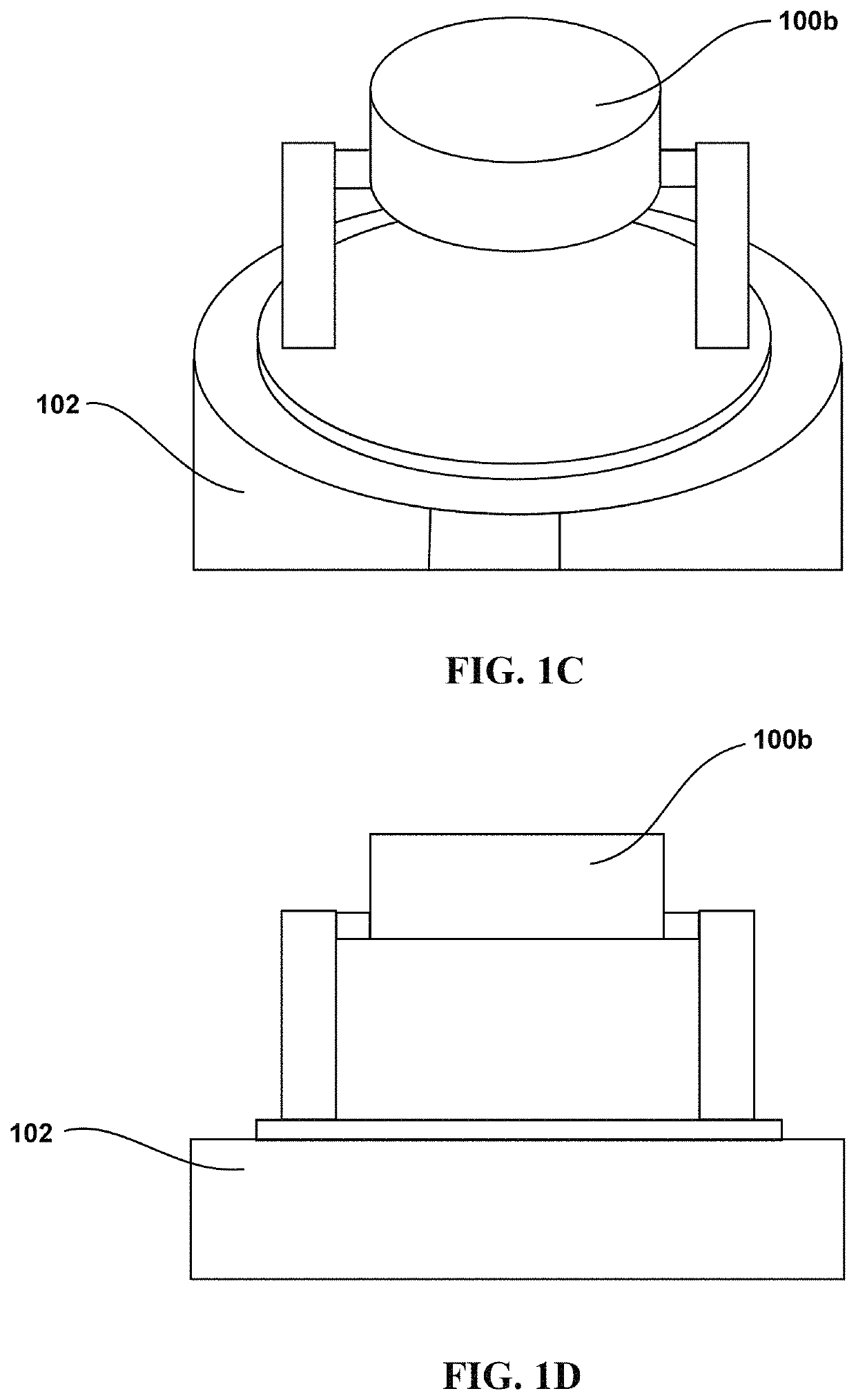
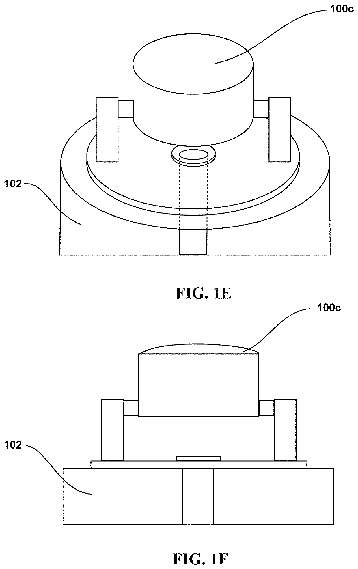
[0037]According to aspects of the present disclosure, a passive microscopic Fabry-Pérot Interferometer (FPI) sensor includes a three-dimensional microscopic optical structure formed on a cleaved tip of the optical fighter using a two-photon polymerization process on a photosensitive polymer by a three-dimensional micromachining device. The three-dimensional microscopic optical structure having a hinged optical layer pivotally connected to a distal portion of a suspended structure. A reflective layer is deposited on a mirror surface of the hinged optical layer while in an open position. The hinged optical layer is subsequently positioned in the closed position to align the mirror surface to at least partially reflect a light signal back through the optical fiber.

[0038]According to aspects of the present disclosure, a method is provided for fabricating a passive optical sensor on a tip of an optical fiber. In one or more embodiments, the method includes perpendicularly cleaving a tip ...


PUM


Abstract

A passive microscopic Fabry-Pérot Interferometer (FPI) sensor includes a three-dimensional microscopic optical structure formed on a cleaved tip of the optical fighter using a two-photon polymerization process on a photosensitive polymer by a three-dimensional micromachining device. The three-dimensional microscopic optical structure having a hinged optical layer pivotally connected to a distal portion of a suspended structure. A reflective layer is deposited on a mirror surface of the hinged optical layer while in an open position. The hinged optical layer is subsequently positioned in the closed position to align the mirror surface to at least partially reflect a light signal back through the optical fiber.

Description

CROSS-REFERENCE TO RELATED APPLICATIONS[0001]This application claims the benefit of priority under 35 U.S.C. § 120 as a continuation-in-part to U.S. patent application Ser. No. 17 / 229,986 entitled “A Monolithically Integrated Microscale Pressure Sensor On An Optical Fiber Tip” and filed 14 Apr. 2021, which in turn claims the benefit of priority under 35 U.S.C. § 119(e) to: (i) U.S. Provisional Application Ser. No. 63 / 172,170 entitled “Mechanically-enabled microscale Fabry-Perot optical cavity on an optical fiber tip,” filed 8 Apr. 2021; (ii) U.S. Provisional Application Ser. No. 63 / 170,054 entitled “A Monolithically Integrated Microscale Pressure Sensor on an Optical Fiber Tip,” filed 17 Apr. 2020; (iii) and U.S. Provisional Application Ser. No. 63 / 011,435 entitled “A Monolithically Integrated Microscale Pressure Sensor on an Optical Fiber Tip,” filed 17 Apr. 2020, the contents and cited references of all of which are incorporated herein by reference in their entirety.[0002]This app...

Claims


Application Information

Patent Timeline
IPC IPC(8): G02B6/293
CPCG02B6/29359G02B6/02033G02B6/29358G02B6/29395G02B6/3518G02B2006/12159
Inventor WILLIAMS, JEREMIAHCHANDRAHALIM, HENGKY
Owner THE UNITED STATES OF AMERICA AS REPRESETNED BY THE SEC OF THE AIR FORCE
Why Eureka
Try Eureka