Nose hair cutter

a nose hair and cutter technology, applied in the field of nose hair cutters, can solve the problems of nose hair injury to the user's nostrils, difficult to efficiently cut nose hairs with the motor-driven device, frequent malfunction and battery replacement, etc., and achieve the effect of smooth nose hair cutting and easy introduction

Active Publication Date: 2021-09-09
ROYAL METAL IND
View PDF0 Cites 0 Cited by
  • Summary
  • Abstract
  • Description
  • Claims
  • Application Information

AI Technical Summary

Benefits of technology

In this design described in this patented technology, there're two ways that make it easy for users to insert their own nails through them: 1. Using circular shapes instead of rectangular ones like those used earlier designs. These circles help guide the nail towards its intended destination without getting stuck during shaving. Additionally, they block off some parts inside the device itself preventing these things from entering. 2. To improve durability with added features such as reinforcement against damage or lubrication between components. Overall, this design improves safety and convenience compared to traditional devices.

Problems solved by technology

The technical problem addressed in this patent is the discomfort, injury, and hygienic concerns associated with traditional nose hair clippers that use small scissors or motor-driven devices. These devices can malfunction, cause bacterial infections, and lead to unnatural or uncomfortable nasal discharge. Additionally, the patent aims to address the difficulty of efficiently cutting nose hairs due to their irregular growth directions. The patent proposes a new technology that overcomes these disadvantages by providing a more effective and hygienic solution for cutting nose hairs.

Method used


Image

  • Nose hair cutter
  • Nose hair cutter
  • Nose hair cutter

Examples


Embodiment Construction

[0043]A preferred embodiment of the present disclosure will be described in more detail below with reference to the accompanying drawings. Specific structures and functions of the embodiment are examples of structural features thereof. The present disclosure is not limited to the embodiment described in the present specification.

[0044]First, the preferred embodiment of the present disclosure will be described below in association with the technology disclosed in Korean Patent No. 1795626. Along with the problems with the disclosed technology, configurations and operational advantages of the present disclosure will be described.

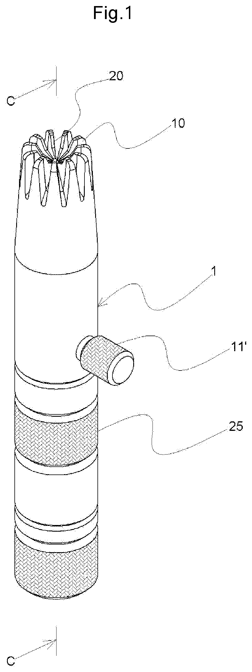
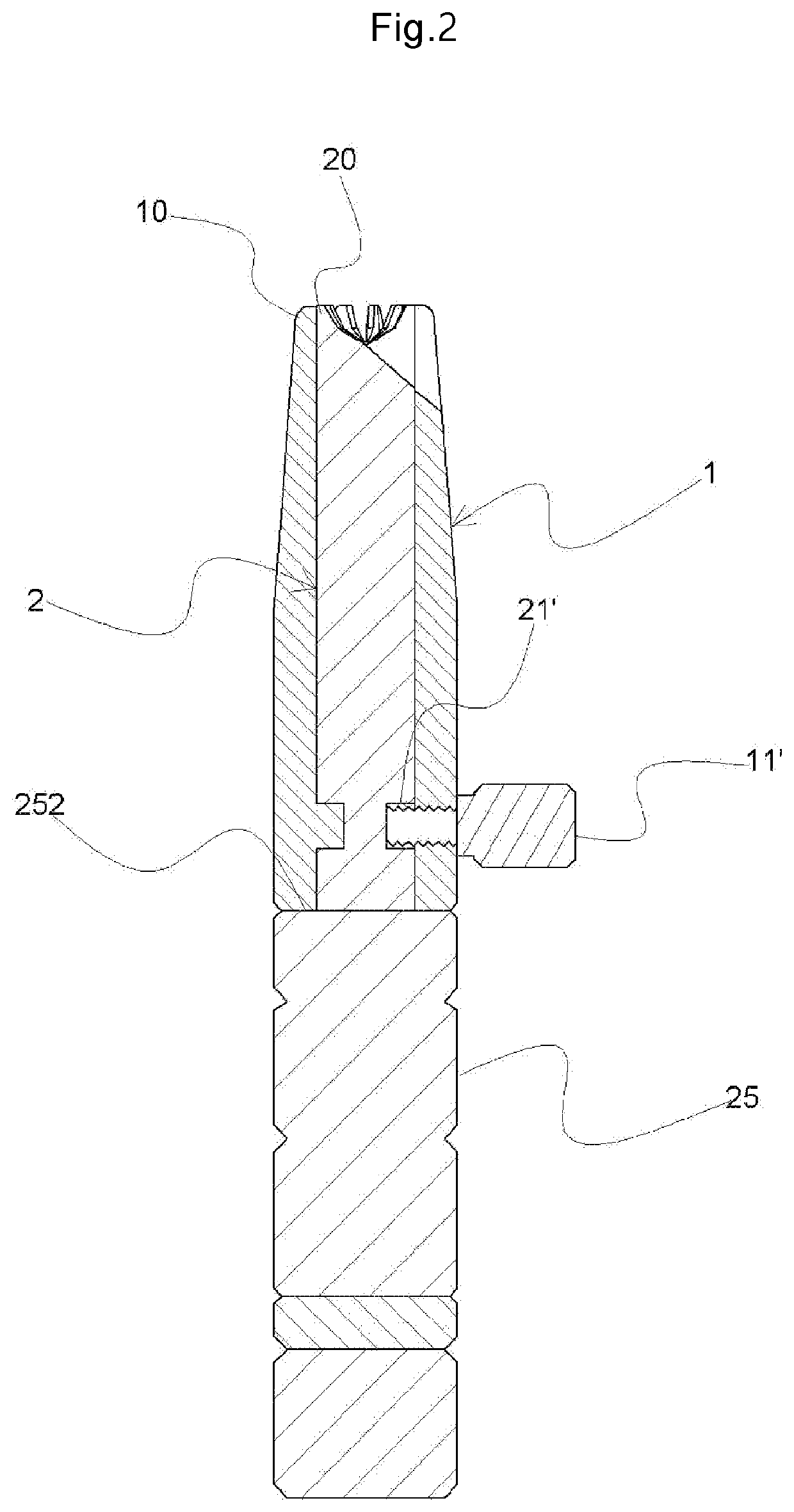
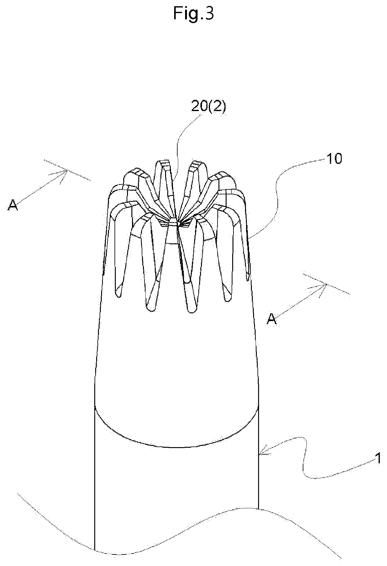
[0045]As illustrated in FIGS. 1 and 2, in a nose hair clipper that is manufactured in the form of a cylinder, a rotatable internal cylindrical body 2 having an internal cutting portion 20 is inserted into a stationary external cylindrical body 1 having an external cutting portion 10. A lower end of the stationary external cylindrical body 1 is fittingly nested...


PUM


Abstract

Proposed is a nose hair clipper including: a stationary external cylindrical body, having an external cutting portion with a plurality of first cutting edges, a plurality of first slits, and a plurality of rounded portions; a rotatable internal cylindrical body, having an internal cutting portion with a plurality of second cutting edges and a plurality of second slits, a convex portion, and a circumferential concave groove, the rotatable internal cylindrical body being inserted into the stationary external cylindrical body, and the plurality of rounded portions of the external cutting portion extending upward to be higher than an upper end of the internal cutting portion by a to predetermined gap; a bolt, screwed into the circumferential concave groove; a handling body, combined with a lower end of the rotatable internal cylindrical body; and an auxiliary cap with a brush and a driver, connected to a lower end of the handling body.

Description


Claims


Application Information

Patent Timeline
Owner ROYAL METAL IND
Why Eureka
Try Eureka