Inflation Pump

a technology of inflation pump and pump body, which is applied in the direction of positive displacement liquid engine, machine/engine, functional valve type, etc., can solve problems such as assembly difficulties

Active Publication Date: 2021-09-09
WU SCOTT
View PDF0 Cites 0 Cited by
  • Summary
  • Abstract
  • Description
  • Claims
  • Application Information

AI Technical Summary

Benefits of technology

[0019]In an example, the through-hole of the head includes a shoulder dividing the through-hole into two sections. One of the two sections of the through-hole adjacent to the coupling hole has an inner diameter smaller than an inner diameter of another of the two sections of the through-hole adjacent to the operating end.
[0020]In an example, the shoulder has an inner diameter gradually reduces from a side thereof adjacent to the operating end towards another side thereof adjacent to the coupling end, forming a conic surface.

Problems solved by technology

Furthermore, due to requirement of the tight coupling between the head and the cylinder, the inflation pump would leak if the processing precision is insufficient, resulting in difficulties in assembly.

Method used


Image

  • Inflation Pump
  • Inflation Pump
  • Inflation Pump

Examples


Embodiment Construction

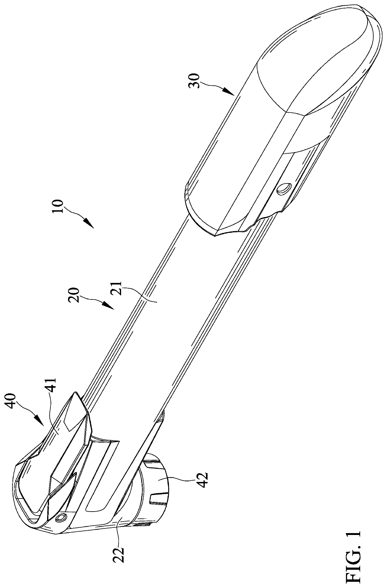
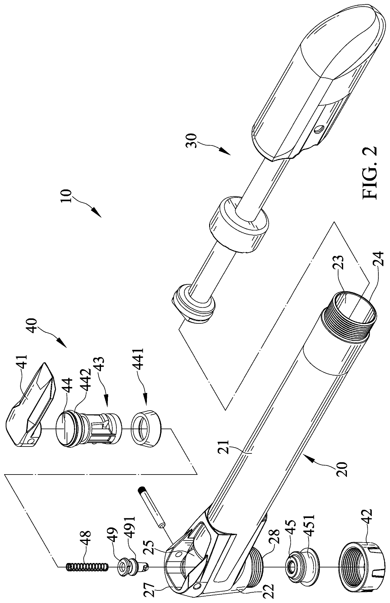
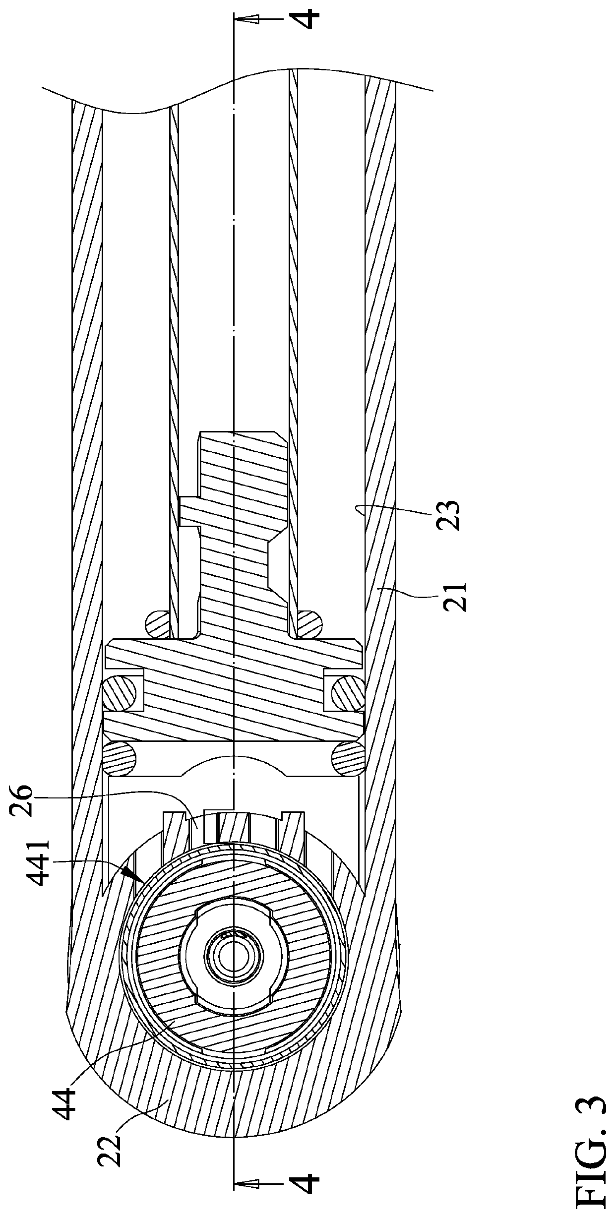
[0030]With reference to FIGS. 1-5, an inflation pump 10 of an embodiment according to the present invention includes a body 20, a pressuring unit 30, and a nozzle unit 40. The body 20 includes a cylinder 21 and a head 22 connected to and integrally formed with the cylinder 21. The head 22 is connected to an end of the cylinder 21. The cylinder 21 includes a pressurizing space 23 therein. Another end of the cylinder 21 opposite to the head 22 includes an opening 24. The head 22 includes a through-hole 25 extending along a longitudinal axis L and having circular cross sections. An intercommunication passage 26 is disposed between the through-hole 25 and the pressurizing space 23 and intercommunicates the through-hole 25 with the pressurizing space 23.

[0031]The head 22 includes an operating end 27 and a coupling end 28 opposite to the operating end 27 along the longitudinal axis L. A junction between the intercommunication passage 26 and the through-hole 25 is located between the opera...


PUM


Abstract

An inflation pump including a body having a cylinder and a head integrally formed with the cylinder. The cylinder includes a pressurizing space. The head includes a through-hole extending along a longitudinal axis. An intercommunication passage is disposed between and intercommunicates with the through-hole and the pressurizing space. A pressurizing unit is slidably received in the pressurizing space and is reciprocally slidable relative to the body. A nozzle unit includes a pressing device disposed in the through-hole. The pressing device includes a push seat having a check ring. The check ring includes an inner side abutting against the push seat and an outer side abutting against a portion of an inner periphery of the through-hole. The portion of the inner periphery of the through-hole is located between the intercommunication passage and the coupling end. The check ring permits air to flow only from the intercommunication passage towards the coupling end.

Description

BACKGROUND OF THE INVENTION[0001]The present invention relates to an inflation pump and, more particularly, to an inflation pump of a simple structure.[0002]Taiwan Patent No. 1472682 discloses a mini inflation pump including a head, a cylinder, a handle, and a fixing device. A nozzle is disposed on a first end of the head, and the cylinder is disposed on a second end of the head. The handle is mounted around the cylinder. A piston rod is mounted in a first end of the handle and is movable relative to the cylinder for pumping air. The fixing device includes a coupling end and a covering end. The coupling end is disposed on a second end of the handle. The covering end selectively covers the nozzle. When the covering end covers the nozzle, the handle and the head are secured together. When the covering end is disengaged from the nozzle, the nozzle can receive an object to be inflated while permitting the handle to displace reciprocally relative the cylinder.[0003]However, to prevent ai...

Claims


Application Information

Patent Timeline
Patent Type & Authority Applications(United States)
IPC IPC(8): F04B33/00
CPCF04B33/005B60S5/04F16K15/20Y10T137/3724
Inventor WU, SCOTT
Owner WU SCOTT
Why Eureka
Try Eureka