
Exhaust gas dilution device

a technology of exhaust gas and dilution device, which is applied in the direction of measurement device, sampling, instruments, etc., can solve the problems of large amount of high-pressure air required for the ejector, measurement accuracy, etc., and achieve the effect of increasing the dilution ratio, smooth movement, and effectively reducing the occurrence of particle loss

Active Publication Date: 2021-09-09
KOREA INST OF MACHINERY & MATERIALS
View PDF0 Cites 0 Cited by
  • Summary
  • Abstract
  • Description
  • Claims
  • Application Information

AI Technical Summary

Benefits of technology

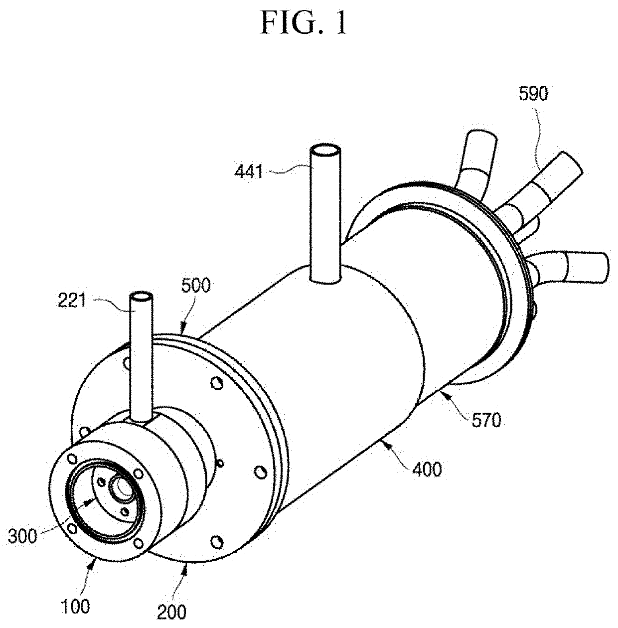
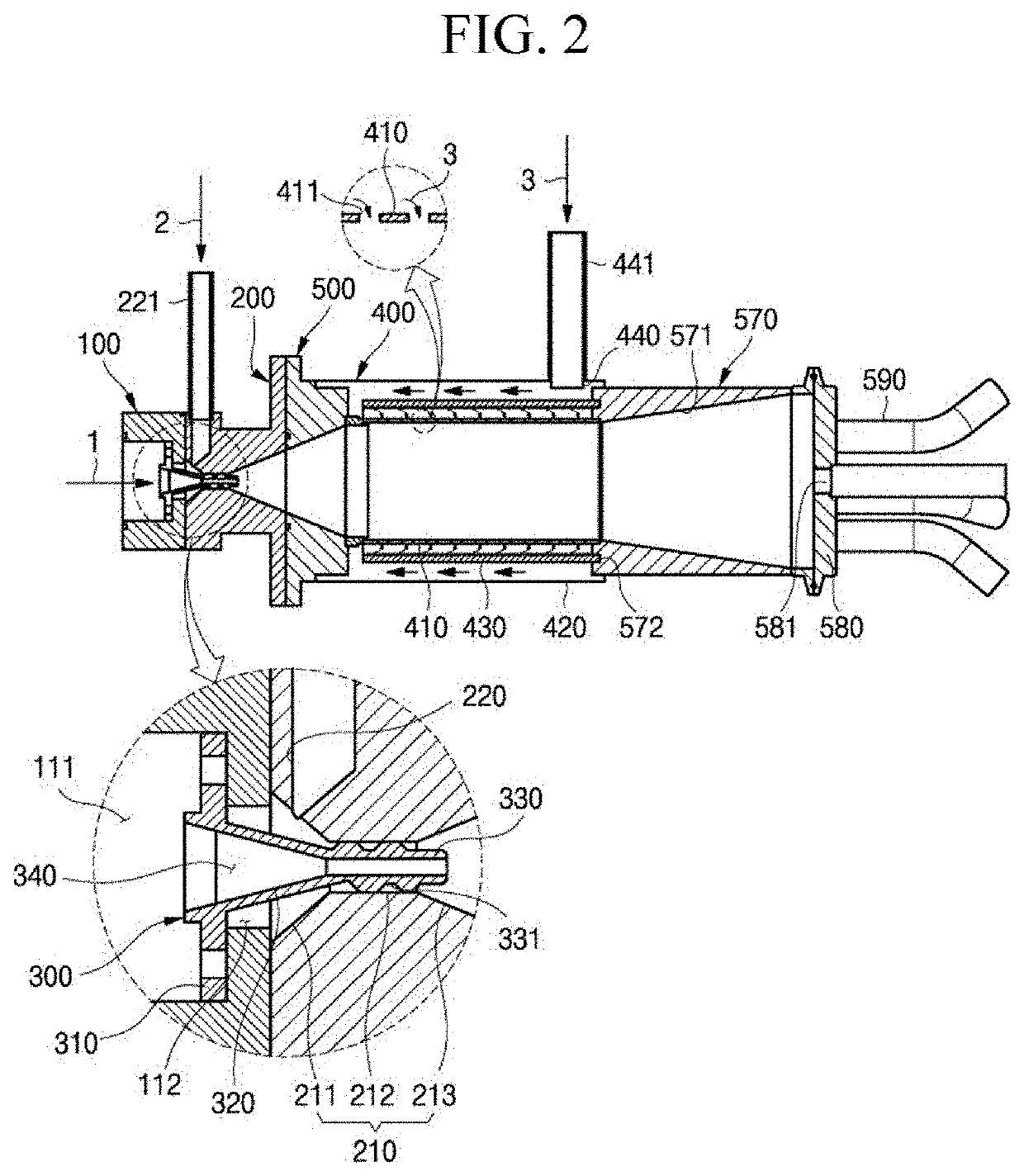
The present invention achieves effective decompression and smooth movement of exhaust gas through the nozzle without the need for compressed air. Secondary dilution air flows into the center direction of the flow path and reduces the number of particles adhered to the interior of the flow path, resulting in a reduction of particle loss during exhaust gas dilution. The exhaust gas is primarily diluted in the ejector unit and secondarily diluted in the dilution part, increasing the dilution ratio. The exhaust gas is mixed with high-temperature primary dilution air and then with room-temperature secondary dilution air to prevent moisture in the exhaust gas from condensing into liquid, improving measurement accuracy of particles.

Problems solved by technology

However, in such a conventional particle dilution device, a problem may occur in measurement accuracy because there are many particles that are lost due to adhesion of the particles to be measured to the inner surface of the mixing chamber.
Also, since a large amount of the dilution gas diluted in the mixing chamber must be sucked through the ejector, a large amount of high-pressure air is required for the ejector.
Therefore, there is a problem that a configuration of a compressor for supplying air to the ejector at high pressure must be added.

Method used


Image

  • Exhaust gas dilution device
  • Exhaust gas dilution device
  • Exhaust gas dilution device

Examples


Embodiment Construction

[0033]Hereinafter, the present invention will be described with reference to the accompanying drawings. As those skilled in the art would realize, the described embodiments may be modified in various different ways, all without departing from the spirit or scope of the present invention. Accordingly, the drawings and description are to be regarded as illustrative in nature and not restrictive, and like reference numerals designate like elements throughout the specification.

[0034]Throughout the specification, when it is described that a part is “connected (in contact with, coupled)” to another part, the part may be “directly connected” to the other element or “connected” to the other part through a third part. Unless explicitly described to the contrary, the word “comprise” and variations such as “comprises” or “comprising” will be understood to imply the inclusion of stated elements but not the exclusion of any other elements.

[0035]Further, terms used in the present specification ar...


PUM

PropertyMeasurementUnit
temperatureaaaaaaaaaa
diameteraaaaaaaaaa

Abstract

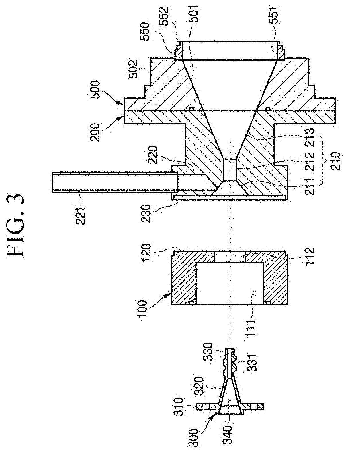
An exhaust gas dilution device according to an exemplary embodiment of the present invention includes a head part, ejector unit, a nozzle part, and a dilution part. The head part has a space part into which an exhaust gas flows and a through-hole formed through the center axis direction to be connected to the space part. The ejector unit is coupled to the head part and has a first discharge hole formed passing through the center axis direction to be connected to the through-hole and connected to a first inlet to which primary dilution air is supplied. The nozzle part is inserted into a first discharge hole through the through-hole and has a second discharge hole that penetrates in the center axis direction so that the exhaust gas flowed into the space part is sucked and ejected into the first discharge hole as the primary dilution air moves through the first discharge hole. The dilution part has a first flow path part into which a primary dilution gas, which is generated and discharged after the exhaust gas and the primary dilution air are mixed in the first discharge hole, flows, and a second flow path part connected to the first flow path part and guiding secondary dilution air to be mixed with the primary dilution gas, and generates a secondary dilution gas as the primary dilution gas and the secondary dilution air are mixed.

Description

TECHNICAL FIELD[0001]The present invention relates to an exhaust gas dilution device. More particularly, the present invention relates to an exhaust gas dilution device that may increase measurement precision.BACKGROUND ART[0002]When a concentration of sampled particles exceeds a measurement range of a particle counter, a particle dilution device as a device for measuring even high concentration sampling particles by being installed at the front end of the particle counter, diluting the sampled particles at a certain dilution ratio, and transferring them to the particle counter is used.[0003]In general, the particle dilution device includes a mixing chamber in which a gas to be measured is flowed and firstly mixed with dilution air to generate a first dilution gas, and an ejector with which dilution air is secondarily mixed with the first dilution gas and transmitted to the particle counter.[0004]However, in such a conventional particle dilution device, a problem may occur in measur...

Claims


Application Information

Patent Timeline
Patent Type & Authority Applications(United States)
IPC IPC(8): G01N1/38G01N1/22
CPCG01N1/38G01N2001/2264G01N2001/2244G01N1/2247G01N2001/2261G01N1/2258
Inventor HAN, BANGWOOWOO, CHANG GYUKIM, HAK JOONKIM, YONG-JIN
Owner KOREA INST OF MACHINERY & MATERIALS
Learn More